
Bi-Center Bit and Drilling Tools with Enhanced Hydraulics

a bi-center bit and hydraulic technology, applied in the direction of drilling accessories, drilling pipes, drilling casings, etc., can solve the problems of ineffective removal of ledges and/or sharp corners, difficult process, and difficulty in achieving the desired quality of drilling long horizontal boreholes

Active Publication Date: 2018-08-16
NAT OILWELL VARCO LP
View PDF5 Cites 0 Cited by
  • Summary
  • Abstract
  • Description
  • Claims
  • Application Information

AI Technical Summary

Benefits of technology

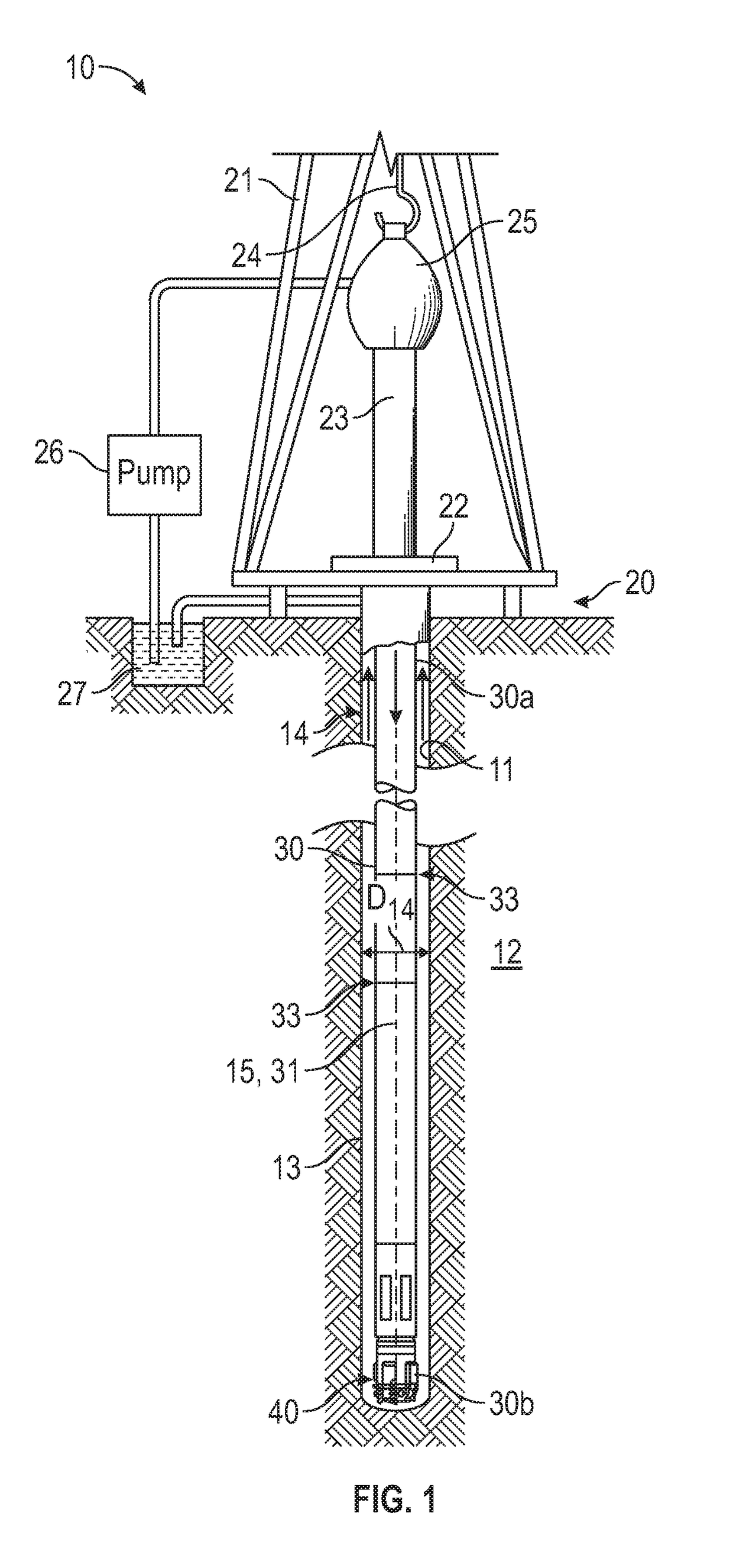
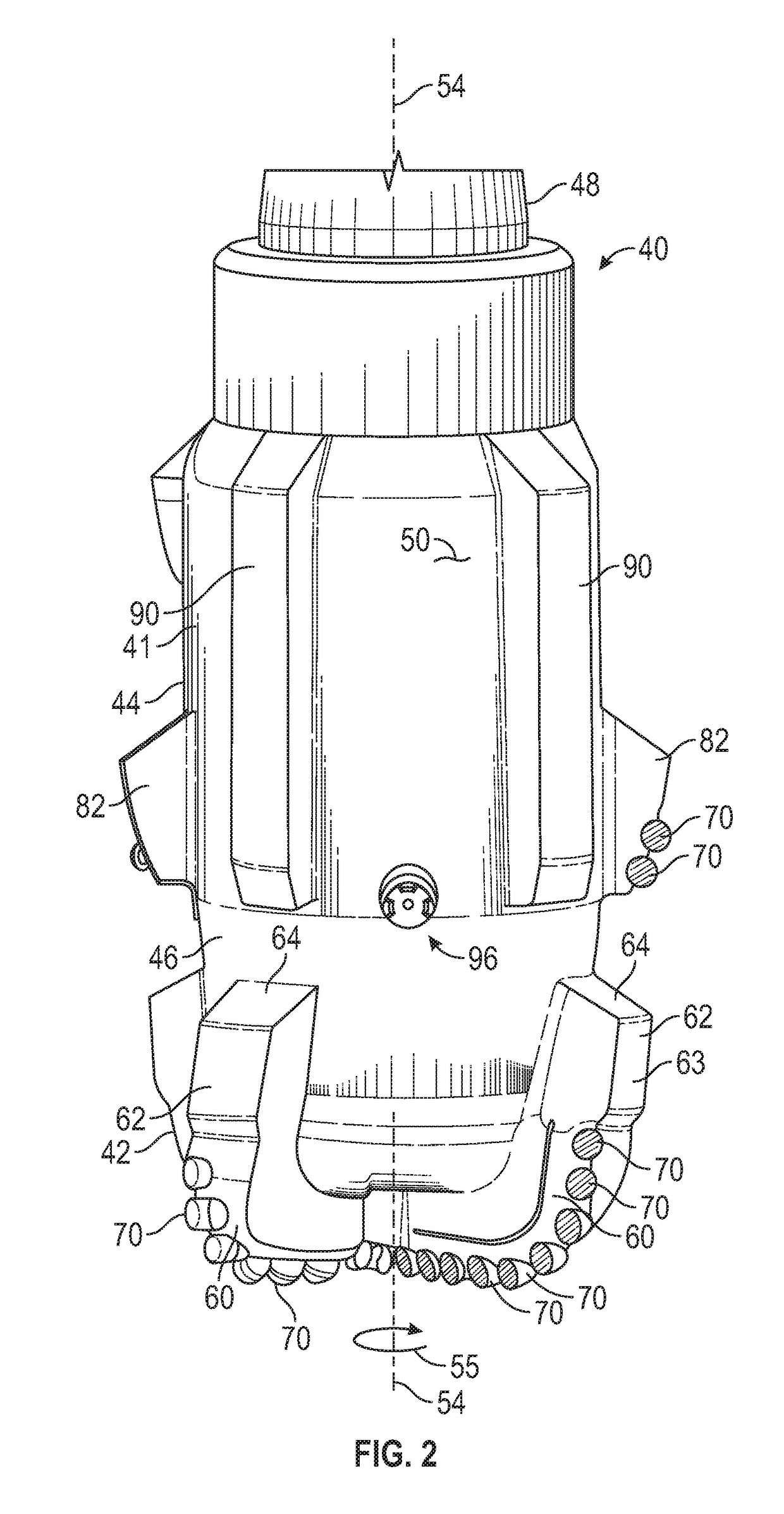
This patent describes drilling tools that address various shortcomings associated with prior devices. The tools include a pilot bit portion coupled to an eccentric reamer, and a fluid passageway extending between the reamer and the pilot bit. One embodiment includes a fluid nozzle directed at the reamer that is positioned at an angle of up to 90 degrees to enhance fluid flow. Another embodiment includes a neck portion between the pilot bit and the eccentric reamer, which tapers to provide better fluid flow. The drilling tools also include stabilizer blades and a buttress to increase the wall thickness of the reamer. Overall, the tools described herein improve drilling performance and efficiency.

Problems solved by technology

In drilling operations, costs are generally proportional to the length of time it takes to drill a quality borehole to the desired depth and location.
This process, known as a “trip” of the drill string, requires considerable time, effort and expense.
However, achieving the desired quality when drilling long horizontal boreholes can be particularly challenging.
In particular, to keep the borehole path as close as possible to horizontal, the driller may have to periodically change the direction of the borehole path because gravity has a tendency to cause the drill bit drop slightly below horizontal.
Unfortunately, repeated corrections can result in the formation of ledges and / or sharp corners in the borehole that interfere with the passage of subsequent tools therethrough.
If a concentric non-expanding reamer having the same or smaller diameter than the drill bit is used with the drill bit, the reamer will generally follow the path of the drill bit and may not be totally effective in removing the ledges and / or sharp corners.
The blades are non-uniformly distributed about the tool, and thus, they occupy less than the total circumference of the tool, thereby making the reamer eccentric.
While necessary for reaming purposes, the addition of reamer blades above the drill bit may have the effect of disrupting the hydraulics that are desirable for removing the drilled cuttings and efficiently conveying them to the surface.
Disruptions to the preferred hydraulics caused by the size, number and placement of the reamer blades may have the detrimental effect of slowing removal of the drilled cuttings.
Poor hydraulics may lead to “bit balling,” a phenomenon where drilled cuttings become compacted on bit features, such as on the cutter elements, or on bit blades.
In turn, this can lead to a decreased rate of penetration and may require tripping the drill string prematurely, each of which can add significantly to the total cost of drilling the well.

Method used


Image

  • Bi-Center Bit and Drilling Tools with Enhanced Hydraulics
  • Bi-Center Bit and Drilling Tools with Enhanced Hydraulics
  • Bi-Center Bit and Drilling Tools with Enhanced Hydraulics

Examples


Embodiment Construction

[0026]The following discussion is directed to various exemplary embodiments. However, the examples disclosed herein have broad application, and that the discussion of any embodiment is meant only to be exemplary of that embodiment, and not intended to suggest that the scope of the disclosure, including the claims, is limited to that embodiment.

[0027]The drawing figures are not necessarily to scale. Certain features and components herein may be shown exaggerated in scale or in somewhat schematic form, and some details of conventional elements may not be shown in interest of clarity and conciseness.

[0028]In the following discussion and in the claims, the terms “including” and “comprising” are used in an open-ended fashion, and thus should be interpreted to mean “including, but not limited to . . . .” Also, the term “couple” or “couples” is intended to mean either an indirect or direct connection. Thus, if a first device couples to a second device, that connection may be through a dire...


PUM


Abstract

A drilling tool includes a pilot bit coupled to an eccentric reamer that has a reaming side and a stabilizing side. A fluid passageway extends between the reamer and the pilot bit, and the tool includes at least one upwardly-directed nozzle in fluid communication with the fluid passageway and positioned on the stabilizing side of the reamer. The reamer may include a plurality of angularly spaced blades on the reaming side that radially extend a first distance, the reamer blades being disposed within a first arcuate segment defined by the two most distant reamer blades. One or more stabilizing blades extend a second distance that is less than the first distance, the stabilization blades being disposed within a second arcuate segment defined by the two most distant reamer blades and that has the angular measure equal to 360 degrees minus the first arcuate segment.

Description

CROSS-REFERENCE TO RELATED APPLICATIONS[0001]This application claims benefit of U.S. provisional patent application Ser. No. 62 / 459,359 filed Feb. 15, 2017, and entitled “Bi-Center Bit and Drilling Tools with Enhanced Hydraulics,” which is hereby incorporated herein by reference in its entirety for all purposes.STATEMENT REGARDING FEDERALLY SPONSORED RESEARCH OR DEVELOPMENT[0002]Not applicable.BACKGROUNDField of the Invention[0003]The present invention relates generally to downhole drilling operations. More particularly, the invention relates to tools for drilling boreholes. Still more particularly, the invention relates to bi-center bits and eccentric reamers for enlarging boreholes during drilling.Background of the Technology[0004]An earth-boring drill bit is connected to the lower end of a drill string and is rotated by rotating the drill string from the surface, with a downhole motor, or by both means. With weight-on-bit (WOB) applied, the rotating drill bit engages the formatio...

Claims


Application Information

Patent Timeline
IPC IPC(8): E21B10/30
CPCE21B10/30E21B10/50E21B10/265
Inventor OMIDVAR, NAVIDSILVA, ROGER H.TAYLOR, NATHAN
Owner NAT OILWELL VARCO LP
Learn More