Locomotive control system

a technology for locomotives and control systems, applied in the direction of railway signalling, railway signalling, signalling indicators on vehicles, etc., can solve the problems of unnecessari complexity of the control system of some vehicles, unfavorable communication between components, and many different communication networks within the vehicl

Active Publication Date: 2018-08-23
GE GLOBAL SOURCING LLC
View PDF1 Cites 53 Cited by
  • Summary
  • Abstract
  • Description
  • Claims
  • Application Information

AI Technical Summary

Benefits of technology

[0027]In one embodiment, a method includes determining whether communication devices that communicate data frames with each other in a time-sensitive network are moving relative to each other, determining an impact of the Doppler effect on when the data frames are received by at least one of the communication devices due to relative movement between the communication devices, and contracting or delaying one or more fetching times of a scheduled communication cycle for at least one of the communication devices based on the impact of the Doppler effect.

Problems solved by technology

The control systems of some vehicles may be complex in that many components communicate with each other.
Not all of these components, however, may communicate signals of the same or similar importance or criticality to operation of the vehicle.
But, using many different communication networks within a vehicle can present unnecessarily complexity.
For example, some components may not be able to communicate with each other without the communications being relayed and / or converted by another component.
As the number of networks and components needed to communicate within a vehicle control system increases, the potential points of failure and complexity of ensuring that communications successful occur increase.
Failure to deliver some data at or within designated times may result in failure of the powered system, which can have significant consequences.
For example, the failure to deliver sensor data to a control system of a locomotive or rail vehicle system can result in the locomotive or rail vehicle system not applying brakes early enough to avoid a collision.
Other control systems may fail to implement protective measures to avoid damage or injury to the systems or other equipment if data is not supplied at or within the designated times. Without timely information, feedback control systems cannot maintain performance and stability.
This can be a time-consuming process, particularly for small changes in the network, and can be prone to errors.
This can result in inefficient and / or ineffective schedules for communications.
As a result, some time sensitive communications may not reach addressed recipients (e.g., readers) in time and / or an unnecessarily reduced amount of bandwidth may be available for use by non-time sensitive communications, such as rate constrained communications and “best effort” communications.
However, the communications received by the TSN for transmission through the network may not include any indication of whether they are a time-sensitive communication or a non-time sensitive communication.
This makes it difficult to configure and schedule all TSN traffic flows in a network.

Method used


Image

  • Locomotive control system
  • Locomotive control system
  • Locomotive control system

Examples


Embodiment Construction

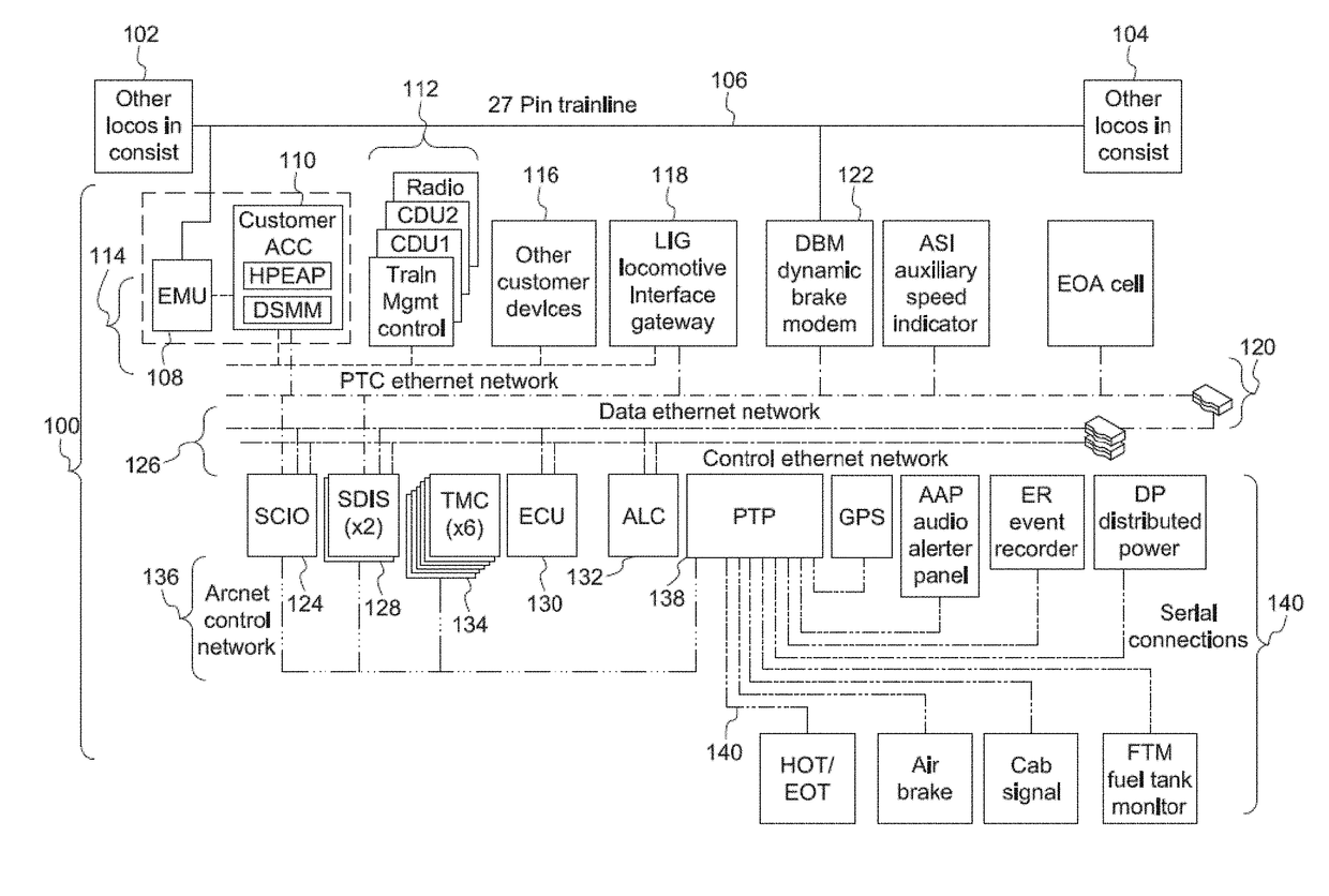
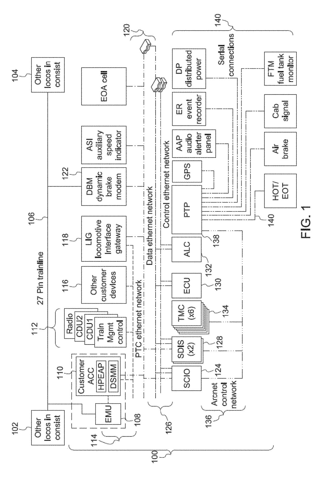
[0076]FIG. 1 illustrates one example of a vehicle control system 100. The vehicle control system 100 may be disposed onboard one or more vehicles of a vehicle system. For example, the control system 100 may be disposed onboard a locomotive of a rail vehicle system formed from the locomotive and one or more other locomotives 102, 104. The locomotives in the vehicle system are communicatively coupled by a wired connection 106, such as a 27-pin trainline cable. Other control systems identical or similar to the control system 100 shown in FIG. 1 may be disposed onboard the other locomotives 102, 104, with the various control systems 100 communicatively coupled (e.g., able to communicate with each other) via the wired connection 106. While the control system 100 is shown as being disposed onboard a locomotive of a rail vehicle system, alternatively, the control system 100 may be disposed onboard another type of vehicle. For example, the control system 100 may be disposed onboard an autom...


PUM


Abstract

A locomotive control system includes a controller configured to control communication between or among plural locomotive devices that control movement of a locomotive via a network that communicatively couples the vehicle devices. The controller also is configured to control the communication using a data distribution service (DDS) and with the network operating as a time sensitive network (TSN). The controller is configured to direct a first set of the locomotive devices to communicate using time sensitive communications, a different, second set of the locomotive devices to communicate using best effort communications, and a different, third set of the locomotive devices to communicate using rate constrained communications.

Description

CROSS-REFERENCE TO RELATED APPLICATIONS[0001]This application is a continuation-in-part of and claims priority to U.S. patent application Ser. No. 15 / 671,204, which was filed 8 Aug. 2017 (the “'204 application”), and which claims priority to U.S. Provisional Patent Application No. 62 / 396,487, which was filed 19 Sep. 2016 (the “'487 application”). This application also is a continuation-in-part of and claims priority to U.S. patent application Ser. No. 15 / 199,368, which was filed 30 Jun. 2016 (the “'368 application”). This application also is a continuation-in-part of and claims priority to U.S. patent application Ser. No. 15 / 485,982, which was filed 12 Apr. 2017 (the “'982 application”). This application also is a continuation-in-part of and claims priority to U.S. patent application Ser. No. 15 / 485,946, which was filed 12 Apr. 2017 (the “'946 application”). This application also is a continuation-in-part of and claims priority to U.S. patent application Ser. No. 15 / 835,056, which w...

Claims


Application Information

Patent Timeline
Patent Type & Authority Applications(United States)
IPC IPC(8): B61L15/00B61L23/00H04L29/08H04L45/50
CPCB61L15/0072B61L15/0036B61L23/005H04L67/12H04L67/322H04L45/50H04L47/11H04L65/80H04L12/56B61L15/0081H04L47/2433H04L67/61H04L65/752
Inventor MONG, TAB ROBERTBUSH, STEPHEN FRANCIS
Owner GE GLOBAL SOURCING LLC
Why Eureka
Try Eureka