
Method for latency improvement of storages using low cost hardware

a storage system and hardware technology, applied in the field of storage systems, can solve the problems of increasing hardware expense, affecting the performance of storage, and increasing the cost of hardware, and achieve the effect of worsening the access latency of the storag

Active Publication Date: 2021-04-20
HITACHI LTD
View PDF6 Cites 0 Cited by
  • Summary
  • Abstract
  • Description
  • Claims
  • Application Information

AI Technical Summary

Benefits of technology

[0006]In related art implementations, there can be drive differences between the TPS and the APS. APS implementations may involve disks which are inexpensive but have large latency and slow storage speeds for analytics processing such as for big data analytics. Flash devices can be used to meet the shorter latency requirements requirement for TPS implementations.
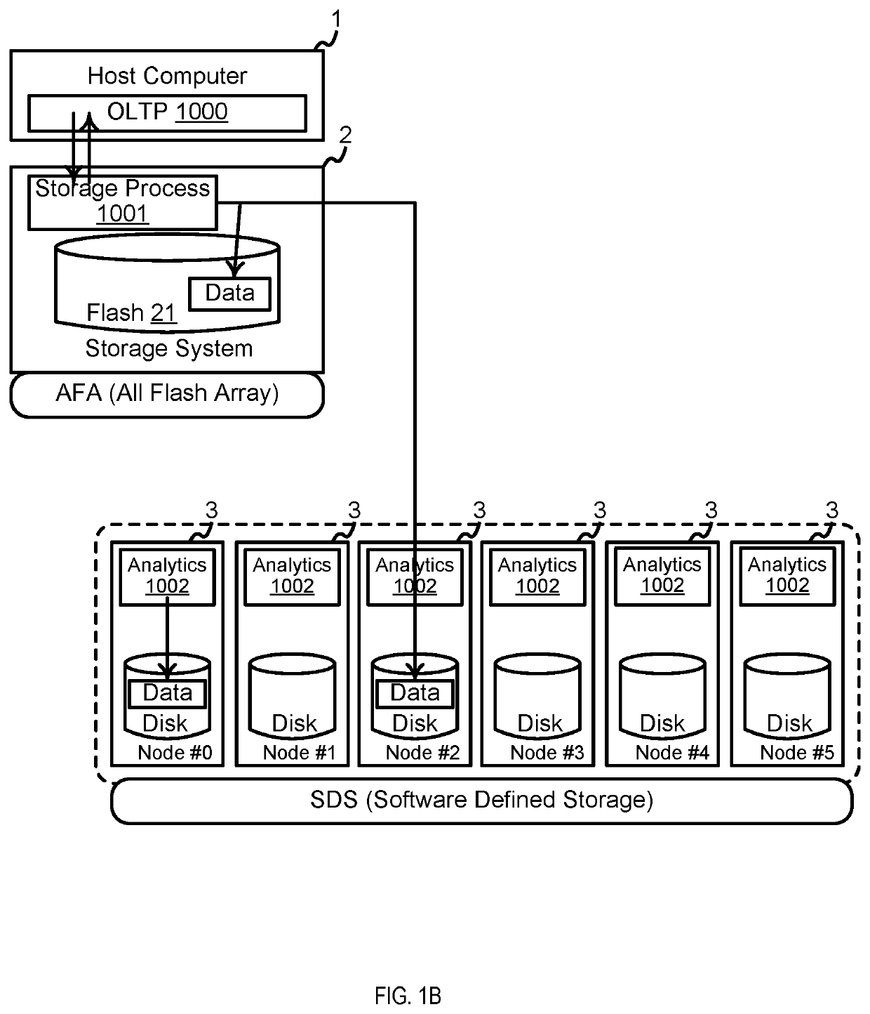
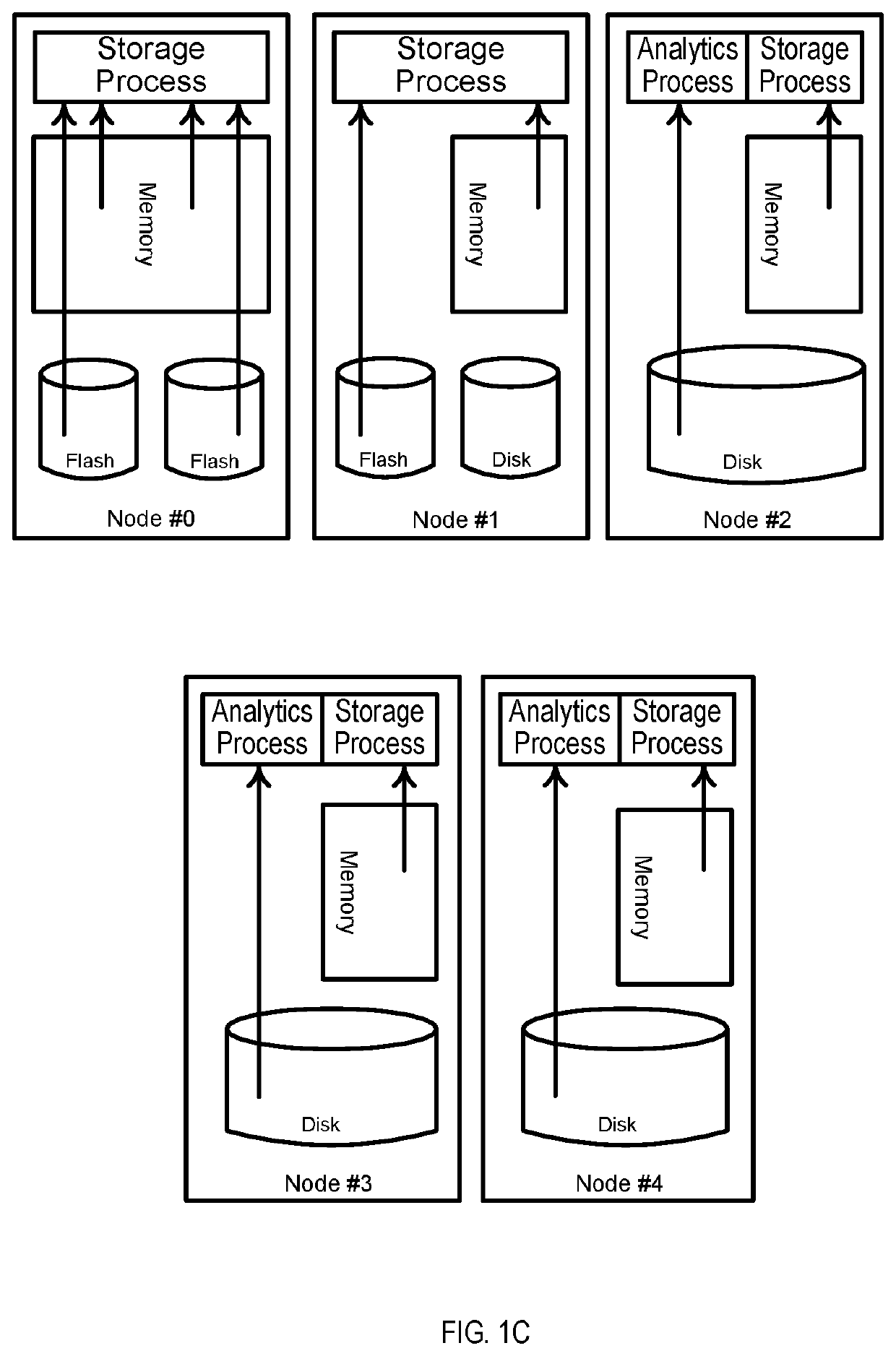
[0008]In example implementations, a storage system selects volumes by considering the kind of disks and the memory size to allocate data to flash or memory as much as possible. Such implementations can reduce the frequency of access to disks during the failure of the storage system. Upon the occurrence of failure on the storage system, the SDS nodes without flash devices load data from disks to memory, and SDS nodes with flash devices are configured to end processes other than storage process.
[0009]Example implementations utilize an application that defines the storage infrastructure. Such implementations may be used by application programmers to develop applications quickly and flexibly, without having to communicate with storage administrators to make storage infrastructure changes.

Problems solved by technology

Thus, such related art storage implementations involve flash in the form of an all flash array (AFA) due to the latency.
Such AFA implementations tend to be expensive.
Therefore, related art TPS implementations can involve standby systems, which increases the hardware expense.
In related art implementations, the access latency of the OLTP becomes worse when the OLTP accesses replication data from the APS.
APS implementations may involve disks which are inexpensive but have large latency and slow storage speeds for analytics processing such as for big data analytics.
Thus, the access latency for OLTP may be delayed when the target of access is changed to volumes on APS from volumes from TPS, which can occur during the failure of the TPS.

Method used


Image

  • Method for latency improvement of storages using low cost hardware
  • Method for latency improvement of storages using low cost hardware
  • Method for latency improvement of storages using low cost hardware

Examples


Embodiment Construction

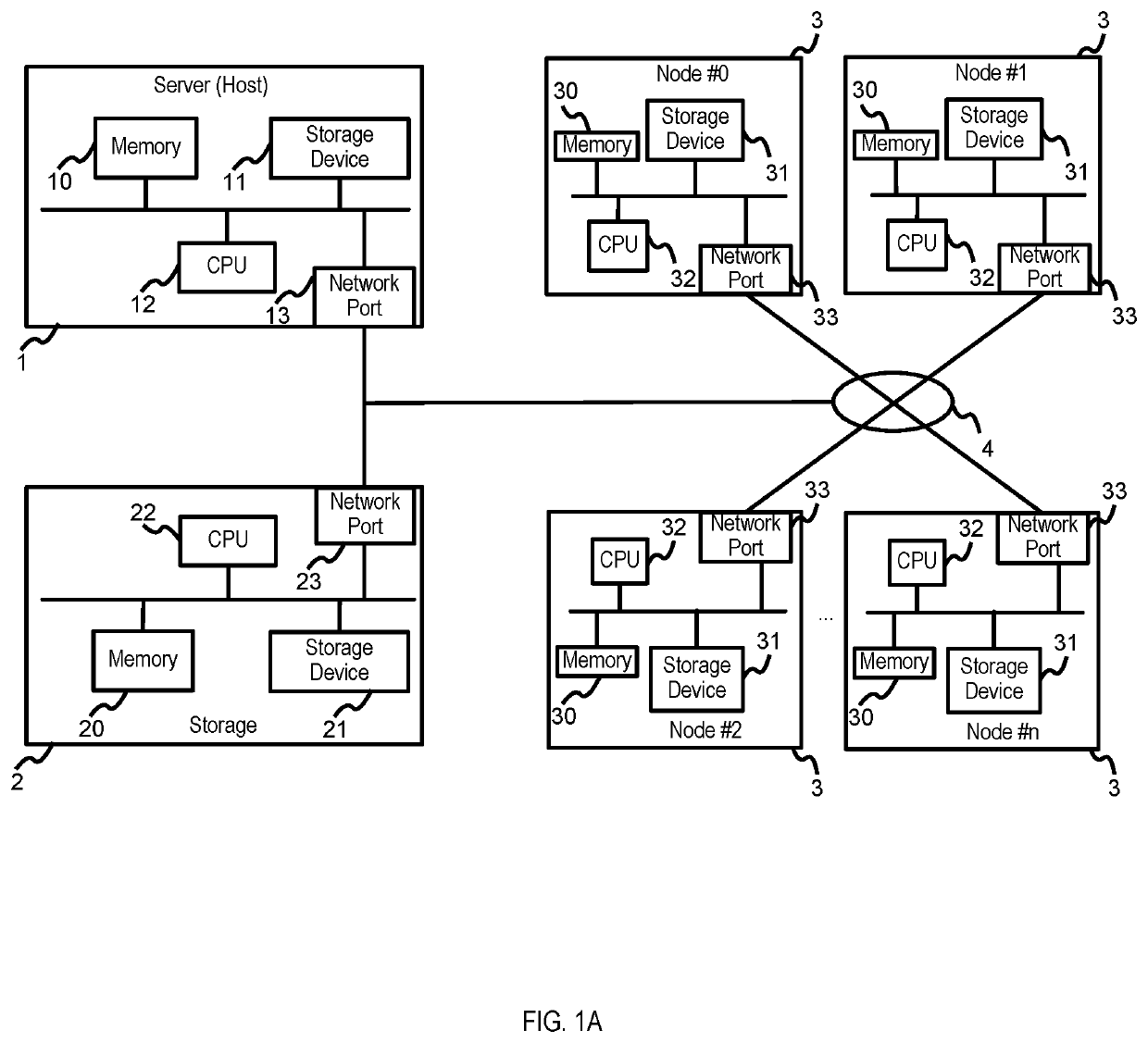
[0027]The following detailed description provides further details of the figures and example implementations of the present application. Reference numerals and descriptions of redundant elements between figures are omitted for clarity. Terms used throughout the description are provided as examples and are not intended to be limiting. For example, the use of the term “automatic” may involve fully automatic or semi-automatic implementations involving user or administrator control over certain aspects of the implementation, depending on the desired implementation of one of ordinary skill in the art practicing implementations of the present application. Selection can be conducted by a user through a user interface or other input means, or can be implemented through a desired algorithm. Example implementations as described herein can be utilized either singularly or in combination and the functionality of the example implementations can be implemented through any means according to the d...


PUM


Abstract

Example implementations described herein are directed to systems and methods involving an application running on a host computer and configured to manage storage infrastructure. The application not only manages resources already allocated to itself, but also manages the allocation and de-allocation of resources to itself. The resources can be allocated and de-allocated based on the type of process being executed, wherein upon occurrence of a failure on a primary storage system, higher priority processes that are executed on connected failover storage system nodes are given priority while the lower priority processes of such failover storage system nodes are disabled.

Description

BACKGROUNDField[0001]The present disclosure is generally related to storage systems, and more specifically, for facilitating latency improvement for storage systems.Related Art[0002]To facilitate Online Transaction Processing (OLTP), the storage system facilitating the OLTP has a latency that is short enough for transaction processing system (TPS). Thus, such related art storage implementations involve flash in the form of an all flash array (AFA) due to the latency. Such AFA implementations tend to be expensive. Moreover, TPS implementations require the down time to be minimized, as well as minimal performance degradation during incidents of system failure. Therefore, related art TPS implementations can involve standby systems, which increases the hardware expense.[0003]If the TPS implementation can copy replication data to volumes on analytics processing system (APS) instead of standby systems, the hardware cost of the standby systems can be reduced. Thus in related art implementa...

Claims


Application Information

Patent Timeline
Patent Type & Authority Patents(United States)
IPC IPC(8): G06F11/20G06F3/06
CPCG06F11/2069G06F3/061G06F3/065G06F3/067G06F3/0611G06F3/0635G06F3/0665G06F3/0679
Inventor SAKASHITA, YUKIHATASAKI, KEISUKE
Owner HITACHI LTD
Learn More