Loudspeaker driver surround

a driver and loudspeaker technology, applied in the direction of loudspeaker diaphragm shape, electrical transducers, electrical apparatus, etc., can solve the problems of reducing the frequency response of the driver, adversely affecting the sound quality of the loudspeaker, and increasing so as to reduce the mass of the surround and resist back pressure

Active Publication Date: 2018-08-23
GP ACCOUSTICS (UK) LIMITED
View PDF12 Cites 4 Cited by
  • Summary
  • Abstract
  • Description
  • Claims
  • Application Information

AI Technical Summary

Benefits of technology

[0008]The present invention is predicated on a realisation that providing the surround with a means to deform in a controlled manner can avoid previously uncontrolled geometric bucklin...

Problems solved by technology

The deformation of the surround due to the back pressure, and the collision of the diaphragm with the surround adversely affect the sound quality produced by the loudspeaker.
However, this increases the mass of the surround, producing a surround having a very nonlinear restoring force, and also gives the driver a very poor frequency response, lowering bass output, breakup frequency and sensitivity.
There is a further deformation problem which arises with traditional surrounds, which is their tendency to ‘buckle’ when they deform.
In the simple example of a surround having a cylindrical roll surface, in order for the diaphragm to move through a...

Method used


Image

  • Loudspeaker driver surround
  • Loudspeaker driver surround
  • Loudspeaker driver surround

Examples


Embodiment Construction

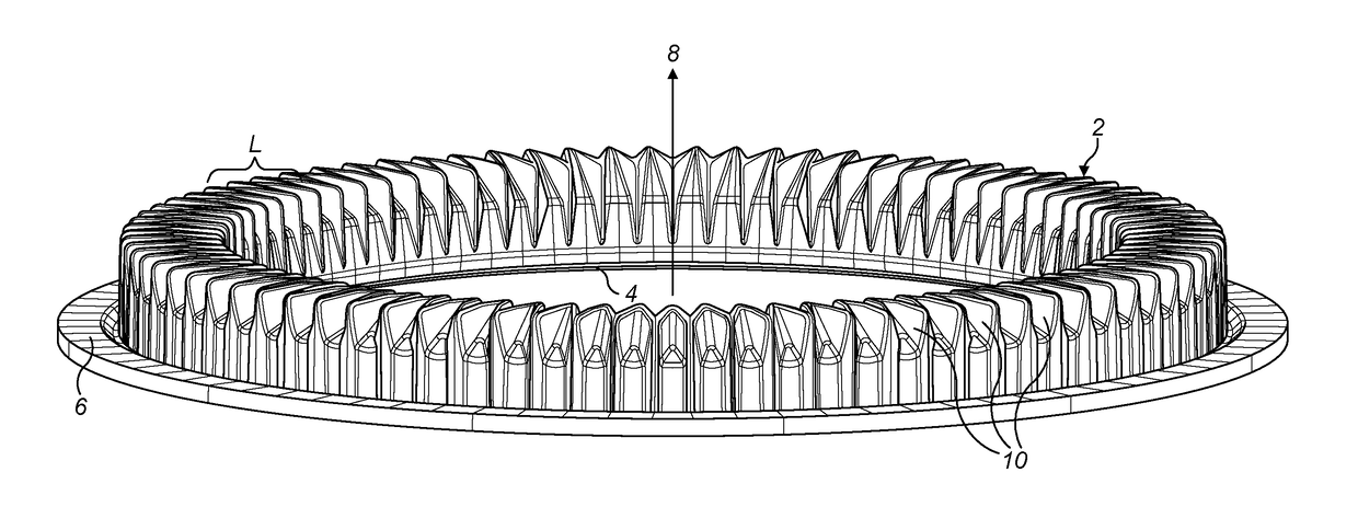
[0030]FIG. 4 shows an annular loudspeaker suspension 2 in its relaxed state (as is the case in all of the subsequent drawings) which has a flat outer circumferential edge 6 for mounting or clamping to the loudspeaker enclosure (not shown) and a flat inner circumferential edge 4 which is configured to be attached to the diaphragm (not shown) or to the voice coil (not shown) of the loudspeaker. The inner and outer edges 4, 6 are in approximately the same plane. In use, the voice coil and the diaphragm vibrate at audio frequencies in the direction of the central axis 8 of the annular surround 2, and the outer edge 6 remains fixed whilst the inner edge 4 reciprocates along axis 8 relative to the outer edge 6 and the loudspeaker enclosure. The suspension 2 is unitary (i.e. formed in one piece) and is formed of a suitably resilient material (such as by being moulded of an elastic material, as is known in the art), and serves to hold the diaphragm / voice coil aligned on the axis 8 throughou...


PUM


Abstract

A loudspeaker driver surround 2 comprises a flexible, generally annular element having a central axis 8 along which in use a diaphragm is driven, an outer edge 6 for fitment to an enclosure and an inner edge 4 for fitment to the diaphragm, with a roll surface which extends between the edges and which projects in the direction of the axis, wherein the roll surface has a shape formed by a plurality of axial corrugations 10 extending generally radially with respect to the annular element between the outer and inner edges thereof, the corrugations being shaped and configured such that the roll surface is non-axisymmetric about the axis, and the arrangement being such that cross-sections of the roll surface which extend radially with respect to the annular element between the outer and inner edges thereof have a substantially constant length at all circumferential positions around the annular element and so that the shape of the said cross-section varies continuously between circumferential positions around the annular element, the corrugations giving the projecting roll surface an order of rotational symmetry of at least 30.

Description

FIELD OF THE INVENTION[0001]The present invention relates to loudspeaker driver surrounds.BACKGROUND ART[0002]A common type of loudspeaker transducer (or driver) has an electromagnetic coil suspended in a strong magnetic field, normally a coil of wire suspended in a gap between the poles of a permanent magnet. When an alternating current electrical audio signal is applied to the voice coil, the coil is forced to move rapidly back and forth due to Faraday's law of induction, which causes a diaphragm or cone attached to the coil to move back and forth, pushing on the air to create sound waves. The electromagnet and the diaphragm vibrate in a direction usually referred to as the driver axis, or the loudspeaker axis. The electromagnet (or voice coil) is housed in a voice coil assembly so that it is free to move reciprocally a pre-determined displacement along the driver axis. Commonly, the voice coil and the diaphragm are circular (in the plane transverse to the driver axis) and there i...

Claims


Application Information

Patent Timeline
IPC IPC(8): H04R9/06H04R7/18H04R9/02
CPCH04R9/06H04R7/18H04R9/025H04R9/02H04R2400/11H04R7/20H04R2307/207H04R7/16
Inventor SKELLETT, ALLAN JAMESOCLEE-BROWN, JACK ANTHONY
Owner GP ACCOUSTICS (UK) LIMITED
Why Eureka
Try Eureka