Rotary machine

Active Publication Date: 2018-08-30
KAWASAKI HEAVY IND LTD +1
View PDF4 Cites 9 Cited by
  • Summary
  • Abstract
  • Description
  • Claims
  • Application Information

AI Technical Summary

Benefits of technology

[0030]The present invention has been configured as described above, and can obtain advantages in that the capability of thermal transport betwee

Problems solved by technology

In particular, in a superconducting rotary machine for a

Method used


Image

  • Rotary machine
  • Rotary machine
  • Rotary machine

Examples


Embodiment Construction

Outline of the Present Invention

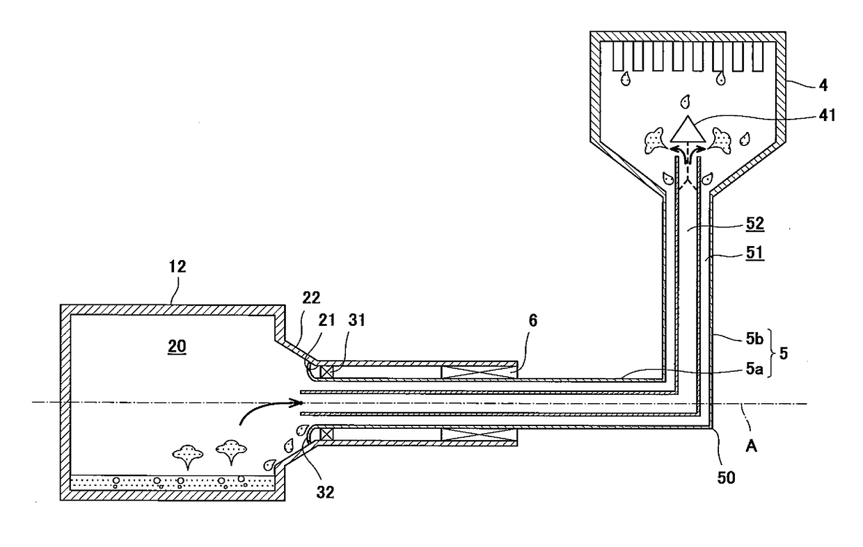
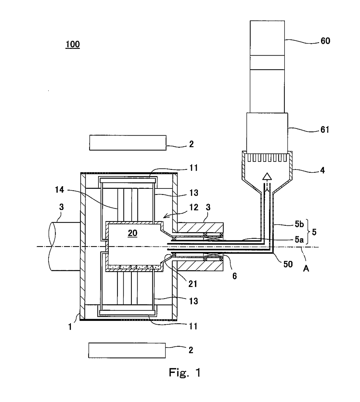
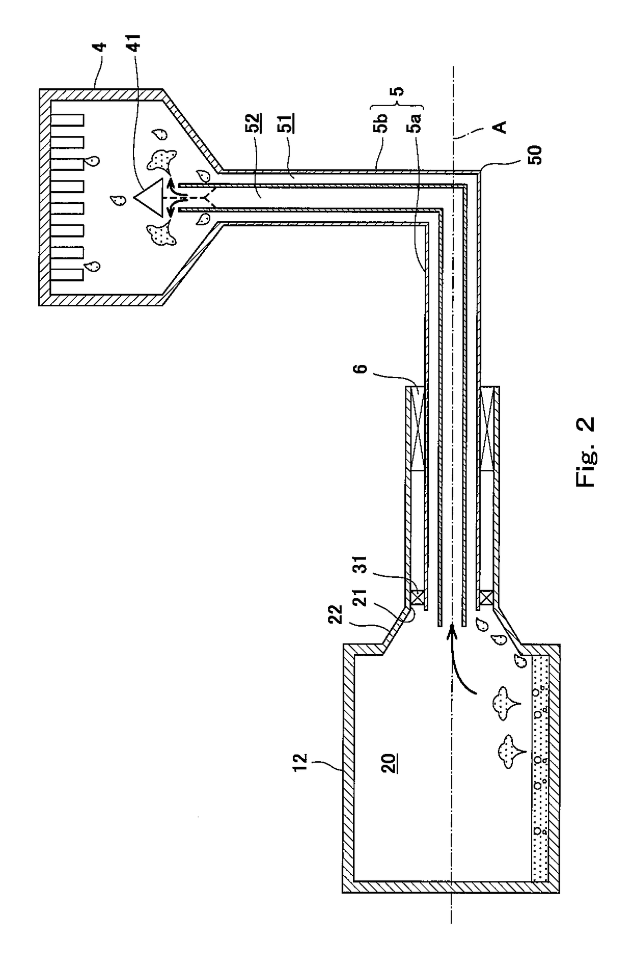
[0037]The present inventors intensively studied the configuration of a rotary machine which cools a cooling target (target to be cooled) such as field poles or armatures inside a rotor, by a thermosiphon action. In particular, the present inventors studied a case where this rotary machine is disposed in a place, for example, inside a marine vessel (ship) where the rotary machine tends to be tilted or shake and cannot be maintained in a horizontal state. In some cases, the thermosiphon action is referred to as a heat pipe action. Specifically, it was found that the problem occurs in the superconducting machine (hereinafter this will be referred to as a conventional rotary machine) disclosed in Patent Literature 1.

[0038]In the conventional rotary machine, a cooling medium (liquid phase cooling medium) generated by liquefaction in a condenser cooled by a cooling device is delivered to a center hollow space (evaporator section) formed inside a rotor of th...


PUM


Abstract

A rotary machine cools a cooling target inside a rotor rotatable around a rotational axis, includes a condenser section disposed outside the rotor and condenses a gas phase cooling medium into a liquid phase cooling medium; an evaporator section disposed inside the rotor, and evaporates the liquid phase cooling medium generated by condensation in the condenser section into the gas phase cooling medium, by heat exchange between the cooling target and the liquid phase cooling medium; and a coupling pipe flows the liquid phase cooling medium and the gas phase cooling medium between the evaporator section and the condenser section, wherein the coupling pipe has a pipe structure in which a liquid phase cooling medium passage flows the liquid phase cooling medium generated by the condensation in the condenser section and a gas phase cooling medium passage flows the gas phase cooling medium generated by evaporation in the evaporator section.

Description

TECHNICAL FIELD[0001]The present invention relates to a rotary machine which cools a cooling target (target to be cooled) inside a rotor which is rotatable around a rotational axis, by a thermosiphon action.BACKGROUND ART[0002]In recent years, a high-temperature superconducting (HTS) magnet around which HTS wires are wound have a broader range of applications. For example, rotary machines such as a superconducting rotary machine using this HTS magnet have been developed.[0003]By the way, the critical temperatures of HTS materials are about 90K. For this reason, it is necessary to cool windings of the HTS wires to about several K to several tens K by use of a cooling device or the like. In particular, in a superconducting rotary machine for a marine vessel (ship), a great thermal load is generated. To secure a sufficient cooling capability, for example, a cooling device such as a GM freezing (refrigerating) device is used. In a case where the superconducting rotary machine for the ma...

Claims


Application Information

Patent Timeline
IPC IPC(8): H02K55/02F28D15/02H02K9/20
CPCH02K55/02F28D15/025F28D15/0275H02K9/20F28D15/02H02K55/04H02K1/32Y02E40/60H02K9/225
Inventor MURASE, YOHEIYANASE, ETSUYAYANAMOTO, TOSHIYUKIIZUMI, MITSURUMIKI, MOTOHIROYAMAGUCHI, KOTA
Owner KAWASAKI HEAVY IND LTD
Why Eureka
Try Eureka