Gas sensor

Active Publication Date: 2011-09-29
NGK INSULATORS LTD
View PDF8 Cites 9 Cited by
  • Summary
  • Abstract
  • Description
  • Claims
  • Application Information

AI Technical Summary

Benefits of technology

[0017]This can achieve a gas sensor which can suppress entry of water adhering to the end portion of the sensor element into the sensor element due t

Problems solved by technology

Moreover, a thermal stress resulting from this temperature gradient may cause cracking.
In a case where the internal combustion engine is driven in this state, the water rapidly vaporizes in the internal space to cause cracking in

Method used


Image

  • Gas sensor
  • Gas sensor
  • Gas sensor

Examples


first preferred embodiment

[0034]

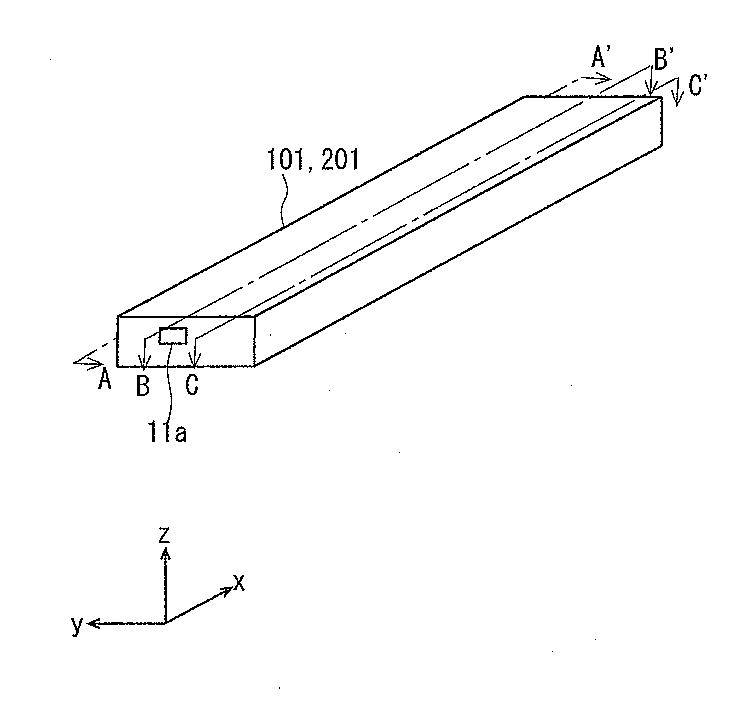
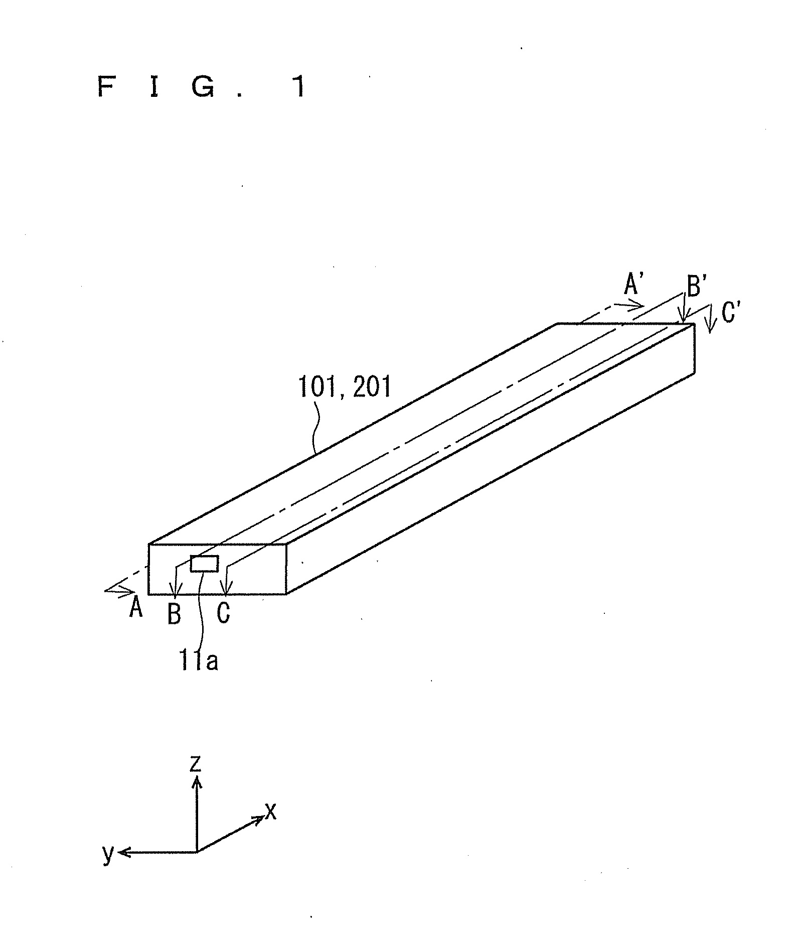
[0035]Firstly, an outline configuration of a gas sensor 100 will be described.

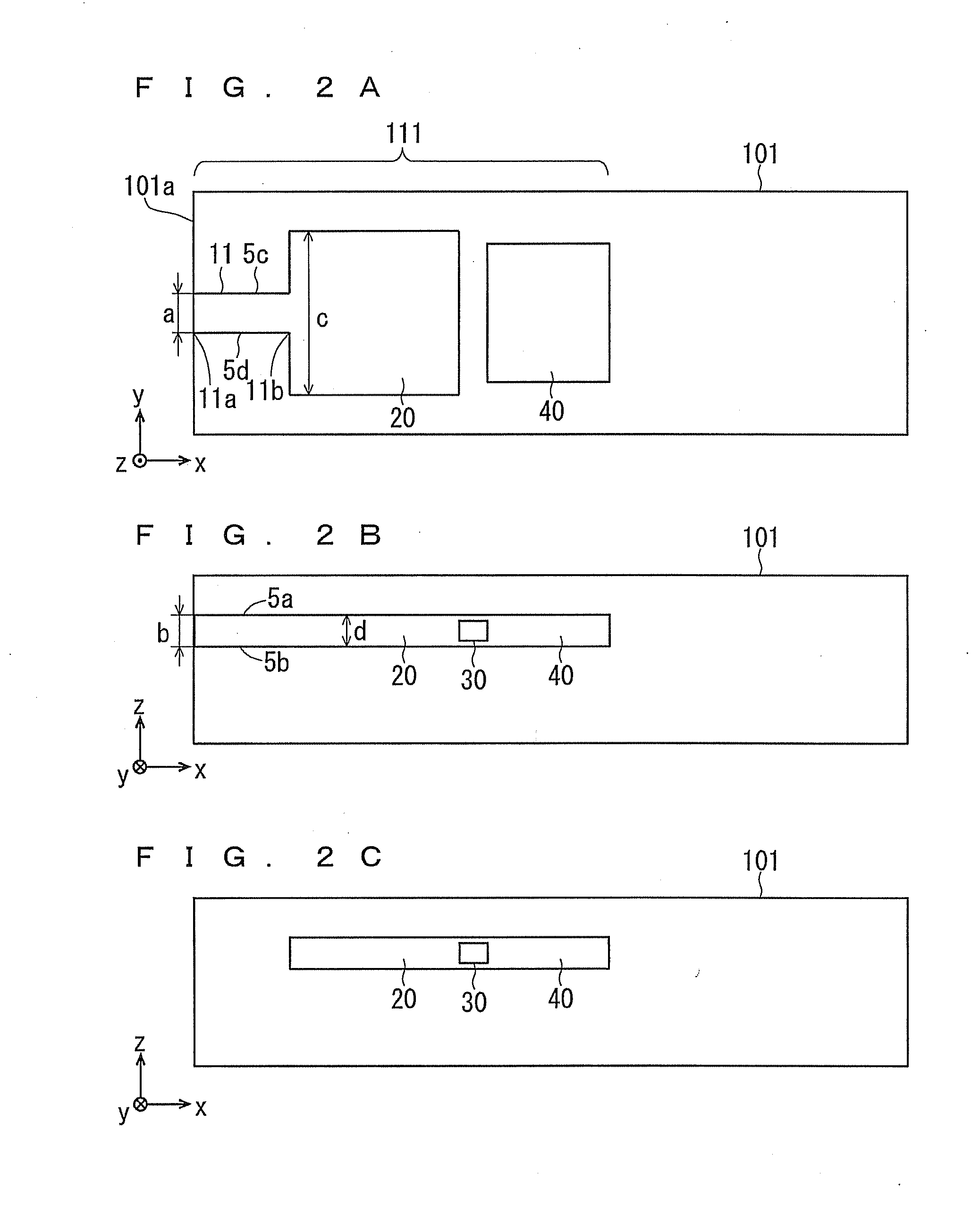
[0036]FIG. 1 is an external appearance perspective view showing an outline of an exemplary configuration of a sensor element 101 of the gas sensor 100. FIG. 1 shows a right-hand xyz coordinate system in which the longitudinal direction of the sensor element 101 is defined as the x-axis (hereinafter, the same is true). FIGS. 2A, 2B, and 2C are schematic cross-sectional views showing outline cross-sections of the sensor element 101 as sectioned at different positions shown in FIG. 1, for explaining the structure of a gas distribution part 111. In FIGS. 2A, 2B, and 2C, for simplification, components other than the gas distribution part 111 are omitted. FIG. 2A shows a cross-section as sectioned along the arrow A-A′ of FIG. 1. FIG. 2B shows a cross-section as sectioned along the arrow B-B′ of FIG. 1. FIG. 2C shows a cross-section as sectioned along the arrow C-C′ of FIG. 1. FIG. 3 is a schematic cross-se...

second preferred embodiment

[0090]In a second preferred embodiment, a configuration in which a gas distribution part is different from that of the gas sensor 100 according to the first preferred embodiment will be described.

[0091]An external appearance perspective view showing an exemplary configuration of a sensor element 201 of a gas sensor 200 according to the second preferred embodiment is identical to that of the gas sensor 100 according to the first preferred embodiment. Therefore, here, FIG. 1 is referred to.

[0092]FIGS. 4A, 4B, and 4C are schematic cross-sectional views showing outline cross-sections of the sensor element 201 sectioned at different positions shown in FIG. 1, for explaining the structure of a gas distribution part 112. In FIGS. 4A, 4B, and 4C, for simplification, components other than the gas distribution part 112 are omitted. FIG. 4A shows a cross-section as sectioned along the arrow A-A′ of FIG. 1. FIG. 4B shows a cross-section as sectioned along the arrow B-B′ of FIG. 1. FIG. 4C shows...

third preferred embodiment

[0100]In a third preferred embodiment, the position where an external communication part is provided is different from that of the gas sensor 100 according to the first preferred embodiment.

[0101]FIG. 5 is an external appearance perspective view showing an outline of an exemplary configuration of a sensor element 301 of a gas sensor 300 according to the third preferred embodiment. FIGS. 6A, B, and 6C are schematic cross-sectional views showing outline cross-sections of the sensor element 301 as sectioned at different positions shown in FIG. 5, for explaining the structure of a gas distribution part 113. In FIGS. 6A, B, and 6C, for simplification, components other than the gas distribution part 113 are omitted. FIG. 6A shows a cross-section as sectioned along the arrow A-A′ of FIG. 5. FIG. 6B shows a cross-section as sectioned along the arrow B-B′ of FIG. 5. FIG. 6C shows a cross-section as sectioned along the arrow C—C′ of FIG. 5. The same components as those of the gas sensor 100 a...


PUM


Abstract

A gas sensor including a sensor element constituted by an oxygen-ion conductive solid electrolyte as a main component and detecting a predetermined gas component in a measurement gas includes: an external communication part having an opening opened to the outside, and introducing the measurement gas from the outside under a predetermined diffusion resistance; an internal space communicating with the external communication part; a first electrode formed on a surface of the internal space; a second electrode formed in a space different from the internal space; and a pumping cell operable to pump out oxygen existing in the internal space when a predetermined voltage is applied between the first electrode and the second electrode. The thickness of the external communication part is 50% or more and 100% or less of the thickness of the internal space.

Description

BACKGROUND OF THE INVENTION[0001]1. Field of the Invention[0002]The present invention relates to a gas sensor including a sensor element and measuring a predetermined gas component in a measurement gas.[0003]2. Description of the Background Art[0004]Conventionally, various measuring apparatuses have been used for recognizing a concentration of a desired gas component in a measurement gas. For example, as a device for measuring a NOx concentration in a measurement gas such as a combustion gas, known is a gas sensor having an electrochemical pumping cell structured by forming a Pt electrode and a Rh electrode on an oxygen-ion conductive solid electrolyte layer, such as a zirconia (ZrO2) layer. In this gas sensor, a diffusion control part communicating with the outside is formed so as to take a measurement gas from the outside into a sensor element and to apply a diffusion resistance suitable for measurement of a concentration of a desired gas component to the measurement gas.[0005]For...

Claims


Application Information

Patent Timeline
IPC IPC(8): G01N27/407
CPCG01N27/4071G01N27/409G01N27/419G01N27/4074G01N27/4072G01N27/417
Inventor HORISAKA, SUMIKOFUJITA, HIROKIMURAKAMI, MIKAITO, TAKASHI
Owner NGK INSULATORS LTD
Why Eureka
Try Eureka