Voltage stabilizing device

Active Publication Date: 2018-06-21
TCL CHINA STAR OPTOELECTRONICS TECH CO LTD
View PDF0 Cites 0 Cited by
  • Summary
  • Abstract
  • Description
  • Claims
  • Application Information

AI Technical Summary

Benefits of technology

[0004]In order to overcome the drawbacks in the prior art, an exemplary embodiments of the invention provides a device capable of controlling and changing feedba

Problems solved by technology

However, since pumping load changes of various output voltages are large and meanwhile there are light and heavy load image changes during driving the panel, resulting in that during this period of

Method used


Image

  • Voltage stabilizing device
  • Voltage stabilizing device

Examples


Embodiment Construction

[0019]Exemplary embodiments of the invention will be described in detail, and examples of the embodiments are illustrated in the accompanying drawings where same numerical references denote same parts. In the following, the embodiments will be described with reference to the accompanying drawings, in order to explain the invention.

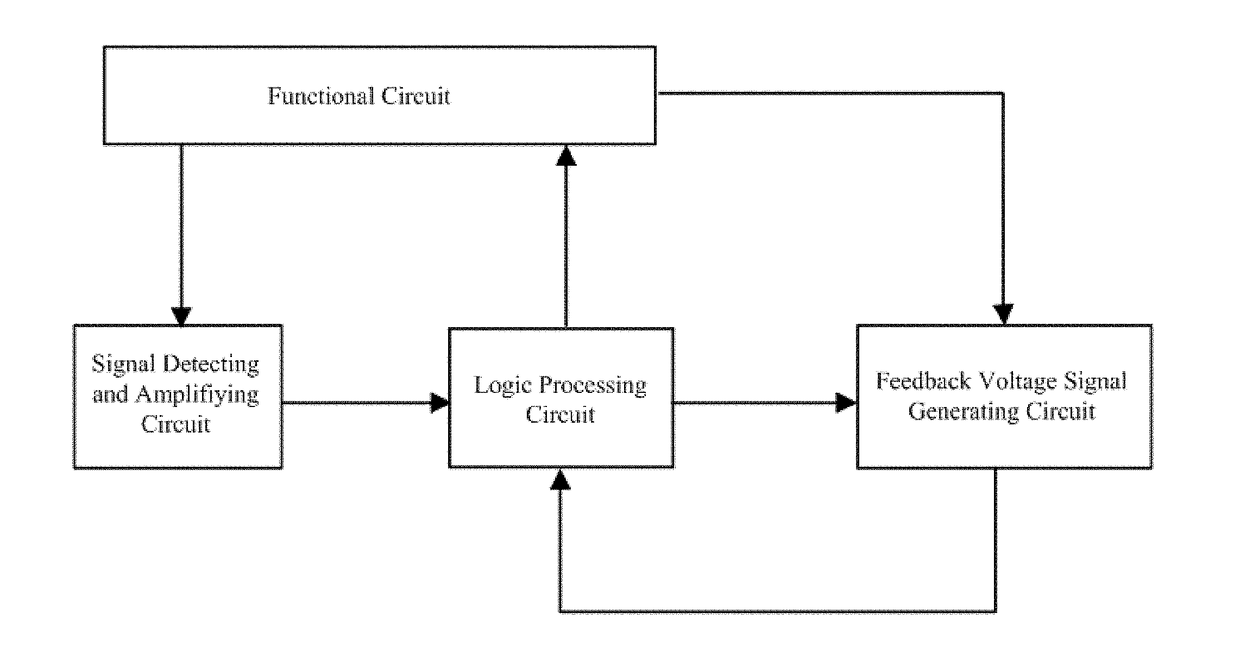
[0020]FIG. 1 is a structural block diagram of a voltage stabilizing device applied for a functional circuit according to an exemplary embodiment of the invention. As illustrated in FIG. 1, the voltage stabilizing device includes a signal detecting and amplifying circuit, a feedback voltage signal generating circuit and a logic processing circuit. The signal detecting and amplifying circuit is configured (i.e., structured and arranged) for detecting an operating voltage of the functional circuit, amplifying the detected operating voltage and outputting the amplified voltage signal to the logic processing circuit. The logic processing circuit is configured f...


PUM


Abstract

The invention provides a voltage stabilizing device. In the voltage stabilizing device, a signal detecting and amplifying circuit detects an operating voltage of the functional circuit, amplifies the detected operating voltage and outputs the amplified voltage signal to a logic processing circuit; the logic processing circuit adjusts a first control signal according to the amplified voltage signal and outputs the adjusted first control signal to a feedback voltage signal generating circuit; the feedback voltage signal generating circuit adjusts a feedback voltage signal according to the adjusted first control signal and outputs the adjusted feedback voltage signal to the logic processing circuit. Moreover, the logic processing circuit further adjusts a second control signal according to the adjusted feedback voltage signal and outputs the adjusted second control signal to the functional circuit, and thereby controls an output voltage of the functional circuit to be kept stable.

Description

BACKGROUND OF THE INVENTION1. Technical Field[0001]The invention relates to a voltage stabilizing device in light and heavy load changes, and the voltage stabilizing device can be applied into fields of backlight and driving of liquid crystal display device.2. Description of Related Art[0002]Nowadays, resolutions of display panels are becoming higher, and correspondingly various currents as required are becoming larger.[0003]However, since pumping load changes of various output voltages are large and meanwhile there are light and heavy load image changes during driving the panel, resulting in that during this period of time, the output voltages would have significant changes in light and heavy load changes caused by decreases of various currents, the output voltages are unstable and ripples are relatively large. Accordingly, the voltage control in light and heavy load changes becomes more important.SUMMARY OF THE INVENTION[0004]In order to overcome the drawbacks in the prior art, an...

Claims


Application Information

Patent Timeline
IPC IPC(8): G09G3/36
CPCG09G3/3648G09G2310/0291G09G3/3406G09G3/36G09G2320/0626
Inventor ZHANG, XIANMINGCAO, DAN
Owner TCL CHINA STAR OPTOELECTRONICS TECH CO LTD
Why Eureka
Try Eureka