

Inverter apparatus
a technology of inverter and circuit, which is applied in the direction of electric variable regulation, process and machine control, instruments, etc., can solve the problems of limited apparatus life, voltage waveform distortion, and difficulty in control, and achieve the effect of reducing the capacitance of a smoothing capacitor connected to the input stage (input side) of the active filter, and reducing the input voltage input of an inverter circui
- Summary
- Abstract
- Description
- Claims
- Application Information
AI Technical Summary
Benefits of technology
Problems solved by technology
Method used
Image

Examples
first preferred embodiment
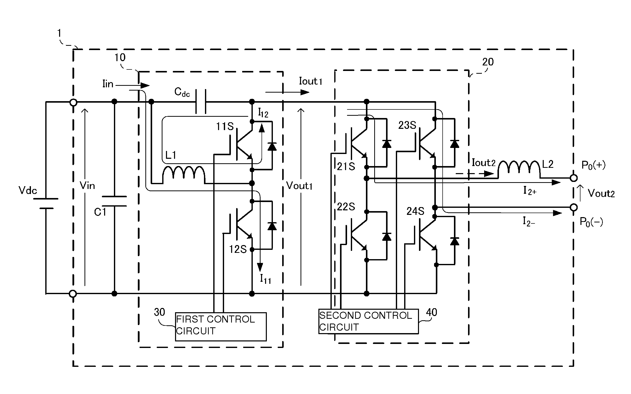
[0035]FIG. 1 is a circuit diagram of an inverter apparatus according to a first preferred embodiment of the present invention. An inverter apparatus 1 according to the present preferred embodiment is preferably used in, for example, a photovoltaic power generation system. Output terminals P0(+) and P0(−) of the inverter apparatus 1 are connected to, for example, a power system load. The inverter apparatus 1 converts DC power converted from solar energy into AC power and outputs the AC power to an AC load. The inverter apparatus 1 of the present preferred embodiment preferably outputs a 200 V AC voltage with a frequency of 50 Hz to the AC load, for example.
[0036]The inverter apparatus 1 includes an active filter circuit 10 and an inverter circuit 20. A DC power supply Vdc and a smoothing capacitor C1 are connected to the input stage (input side) of the active filter circuit 10. The DC power supply Vdc is, for example, a solar battery panel. Hereinafter, an input voltage input from th...
second preferred embodiment
[0066]Hereinafter, a second preferred embodiment of the present invention will be described. Unlike the first preferred embodiment, the second preferred embodiment has a configuration in which the rectifier device 11S according to the first preferred embodiment includes a diode and the switch devices include MOSFETs.
[0067]FIG. 12 is a circuit diagram of an inverter apparatus according to the second preferred embodiment. An inverter apparatus 1A according to the second preferred embodiment includes an active filter circuit 11 and an inverter circuit 21. The active filter circuit 11 includes a capacitor Cdc, an inductor L1, a diode (rectifier device) D1, and a switch device 3S. The capacitor Cdc is connected in series with a high-potential-side line of the active filter circuit 10. The cathode of the diode D1 is connected to the output side of the diode D1. The inductor L1 is connected between the input side of the capacitor Cdc and the anode of the diode D1. The drain of the switch d...
third preferred embodiment
[0072]Hereinafter, a third preferred embodiment of the present invention will be described. An inverter apparatus according to the present preferred embodiment has a configuration in which an insulating DC-DC converter is provided between the input stage (input side) of the smoothing capacitor C1 of the second preferred embodiment and the DC power supply Vdc.
[0073]FIG. 13 is a circuit diagram of an inverter apparatus according to the third preferred embodiment. The active filter circuit 11 and the inverter circuit 21 provided in an inverter apparatus 1B preferably are the same as those in the second preferred embodiment. Note that the inverter apparatus 1B may have a configuration including the active filter circuit 10 and the inverter circuit 20 according to the first preferred embodiment.
[0074]On the primary side of an insulating DC-DC converter 13, a full-bridge circuit is provided and includes switching devices 51S, 52S, 53S, and 54S made of MOSFETs. A control circuit is connect...
PUM
 Abstract
Description
Claims
Application Information