System for controlling rotary electric machines to reduce current ripple on a direct current bus

a technology of rotary electric machines and direct current, which is applied in the direction of electronic commutators, motor/generator/converter stoppers, dynamo-electric converter control, etc., can solve the problems of increasing the cost and weight of the vehicle, reducing fuel economy, and prone to error in the control of the rotary machine (e.g., the rotational speed or commanded torque of the electric motor). the effect of reducing the ripple current and reducing the direct current rippl

Active Publication Date: 2012-09-20
DEERE & CO
View PDF18 Cites 32 Cited by
  • Summary
  • Abstract
  • Description
  • Claims
  • Application Information

AI Technical Summary

Benefits of technology

[0004]In accordance with one embodiment, a system is capable of controlling the propulsion of a vehicle with reduced ripple current on the direct current bus. The system comprises a first motor for applying rotational energy to a respective first wheel of the vehicle. A second motor is arranged for applying rotational energy to a respective second wheel of the vehicle. A first inverter is coupled to the first motor, where the first inverter is capable of receiving direct current electrical energy from the direct current bus. The first inverter is configured to provide a first group of alternating currents with a corresponding reference phase. A second inverter is coupled to the second motor. The second inverter is capable of receiving direct current electrical energy from the direct current bus. The second inverter is configured to provide a second group of alternating currents with a phase shift with respect to the reference phase, such that the phase shift is effective to reduce the direct current ripple on the direct current bus.

Problems solved by technology

For example, in certain instances the current ripple on the direct current bus might be characterized as a transiently lower-than-expected direct current on the direct current bus or undesired fluctuations in the direct current over time on the direct current bus that potentially makes the control of the rotary machines (e.g., electric motor rotational speed or commanded torque) prone to error.
However, greater capacitive filtering may increase the cost and weight of the vehicle, which can lead to reduced fuel economy.

Method used


Image

  • System for controlling rotary electric machines to reduce current ripple on a direct current bus
  • System for controlling rotary electric machines to reduce current ripple on a direct current bus
  • System for controlling rotary electric machines to reduce current ripple on a direct current bus

Examples


Embodiment Construction

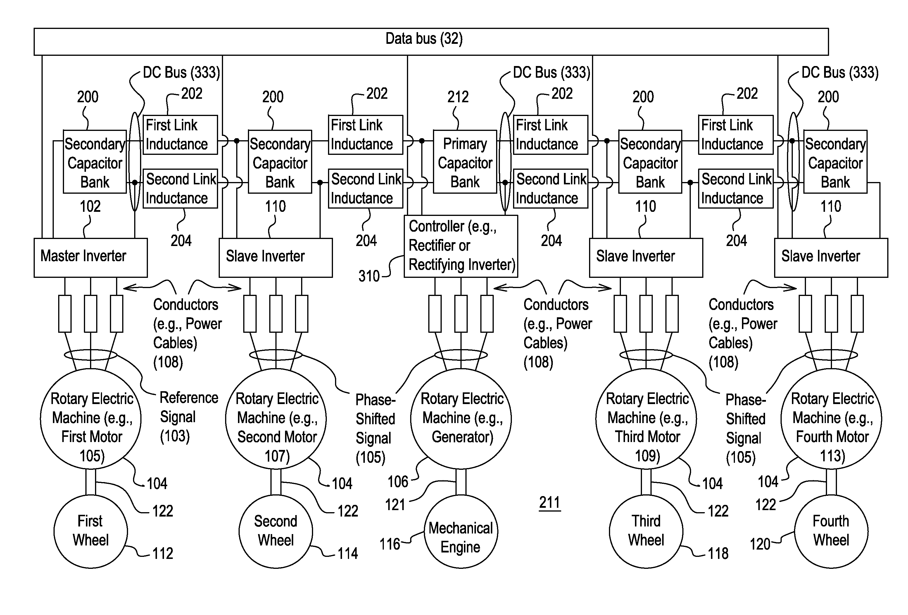
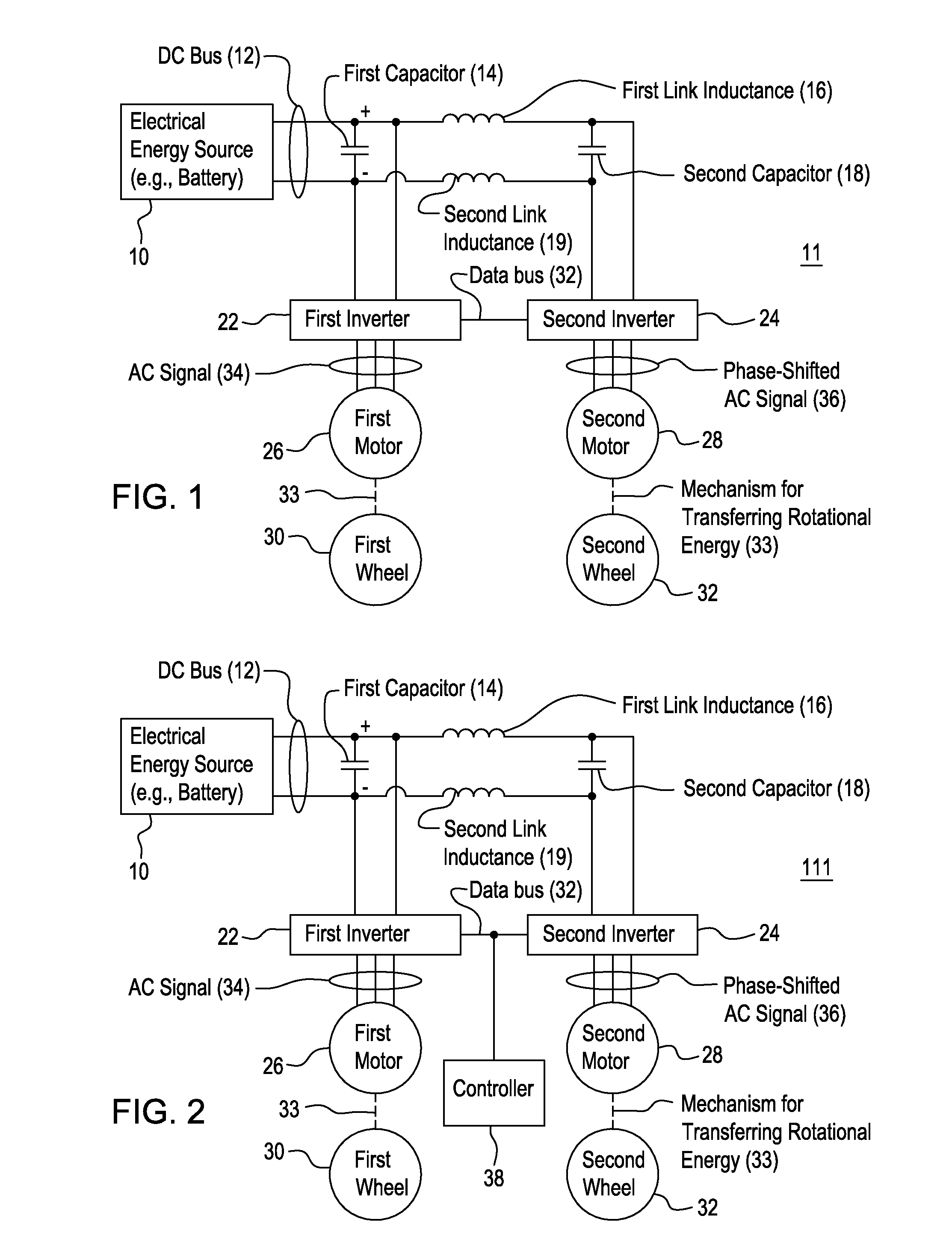
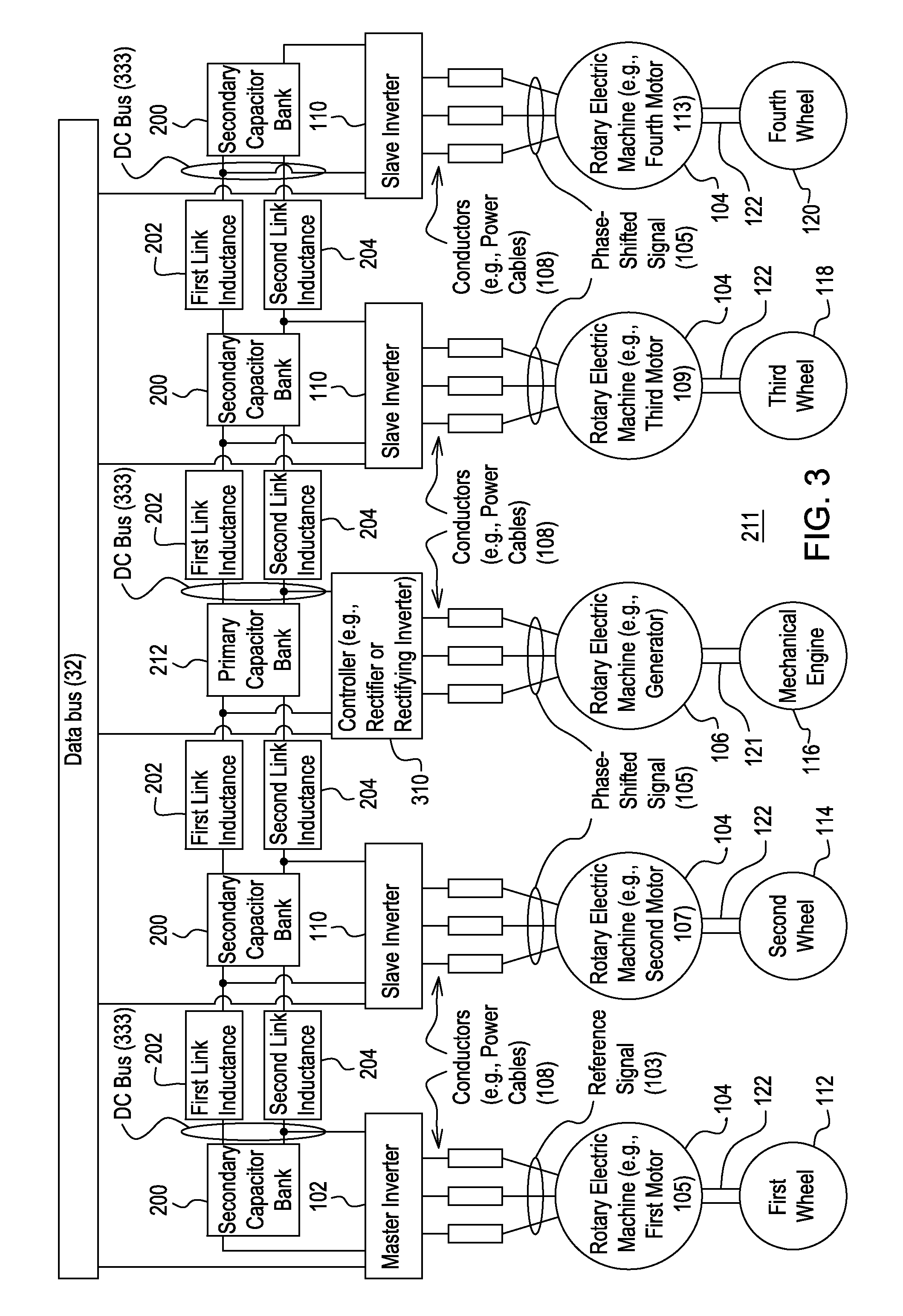
[0009]Ripple refers to variation in the otherwise direct current (DC) or voltage of the direct current bus. Ripple may be modeled as an alternating current signal component (e.g., a generally saw-tooth waveform) of lower magnitude that is combined with the direct current component of greater magnitude to form an aggregate signal on the direct current bus. The peak-to-peak magnitude of the ripple or the root-mean-square magnitude of the ripple may be expressed as a percentage of the direct current component or of the aggregate signal on the direct current bus.

[0010]A capacitor or capacitor bank may be associated with a ripple rating, which is the maximum current that can be applied to the capacitor at a corresponding frequency (e.g., switching frequency of an inverter) of the ripple current.

[0011]In accordance with one embodiment, FIG. 1 shows a system 11 that is capable of controlling the propulsion of a vehicle with reduced current ripple or ripple current on the direct current (DC...


PUM


Abstract

The system comprises a first motor for applying rotational energy to a respective first wheel of the vehicle. A second motor is arranged for applying rotational energy to a respective second wheel of the vehicle. A first inverter is coupled to the first motor, where the first inverter is capable of receiving direct current electrical energy from the direct current bus. The first inverter is configured to provide a first group of alternating currents with a corresponding reference phase. A second inverter is coupled to the second motor. The second inverter is capable of receiving direct current electrical energy from the direct current bus. The second inverter is configured to provide a second group of alternating currents with a phase shift with respect to the reference phase, such that the phase shift is effective to reduce the direct current ripple on the direct current bus.

Description

[0001]This document claims priority based on U.S. provisional application Ser. No. 61 / 453,169, filed on 16 Mar. 2011 and entitled SYSTEM FOR CONTROLLING ROTARY ELECTRIC MACHINES TO REDUCE CURRENT RIPPLE ON A DIRECT CURRENT BUS, under 35 U.S.C. 119(e).FIELD OF THE INVENTION[0002]This invention relates to system for controlling rotary electric machines to reduce current ripple on a direct current bus.BACKGROUND[0003]In the prior art, a vehicle may be configured with multiple rotary electric machines that are controlled by a group of respective inverters. The rotary electric machines may comprise one or more alternating current drive motors, one or more generators, or both. Each of the inverters may draw direct current from a direct current data bus and convert it into alternating current signals with corresponding phases for each rotary electric machine. As each inverter demands direct current to generate alternating current of one or more phases, the direct current on the direct curr...

Claims


Application Information

Patent Timeline
Patent Type & Authority Applications(United States)
IPC IPC(8): H02P6/00
CPCB60L15/007B60L15/20Y02T10/7275B60L2270/147Y02T10/648B60L2220/42H02M1/14H02P5/74H02P27/06B60L2210/40B60L2220/46B60L2240/529Y02T10/64Y02T10/72
Inventor SINGH, BRIJ N.
Owner DEERE & CO
Why Eureka
Try Eureka