Pfc LED driver capable of reducing current ripple

a technology of led drivers and current ripples, applied in the direction of lighting devices, electrical equipment, light sources, etc., can solve the problems of large ripple, inconvenient operation, and substantial degraded luminous efficiency, so as to reduce the current ripple of leds and improve the luminous efficiency without compromising the power factor

Inactive Publication Date: 2014-02-13
WANG YEN HUI
View PDF0 Cites 18 Cited by
  • Summary
  • Abstract
  • Description
  • Claims
  • Application Information

AI Technical Summary

Benefits of technology

[0022]One objective of the present invention is to disclose a PFC LED driver capable of reducing the current ripple of LEDs to improve the luminous efficiency without compromising the power factor.

Problems solved by technology

For general linear LED drivers, inferior efficiencies are their major disadvantages.
However, although the electrical power efficiency is improved, the luminous Efficiency—the ratio of luminous flux to electrical power—is substantially degraded due to a fact that, the LED currents in FIG. 1 and FIG. 2 are generated to have waveforms analog to the waveform of the full-wave rectified line input voltage to meet a high PFC requirement, and thereby has a large ripple.
For LEDs, large current ripples are adverse to luminous efficiency and can cause a flicker phenomenon that is uncomfortable to human eyes.
To have a good luminous efficiency and eliminate the flicker phenomenon, the waveform of the LED current is expected to be as close to a DC line as possible, but with the LED current close to a DC line, the power factor can be greatly compromised.

Method used


Image

  • Pfc LED driver capable of reducing current ripple
  • Pfc LED driver capable of reducing current ripple
  • Pfc LED driver capable of reducing current ripple

Examples


Embodiment Construction

[0058]The present invention will be described in more detail hereinafter with reference to the accompanying drawings that show the preferred embodiments of the invention.

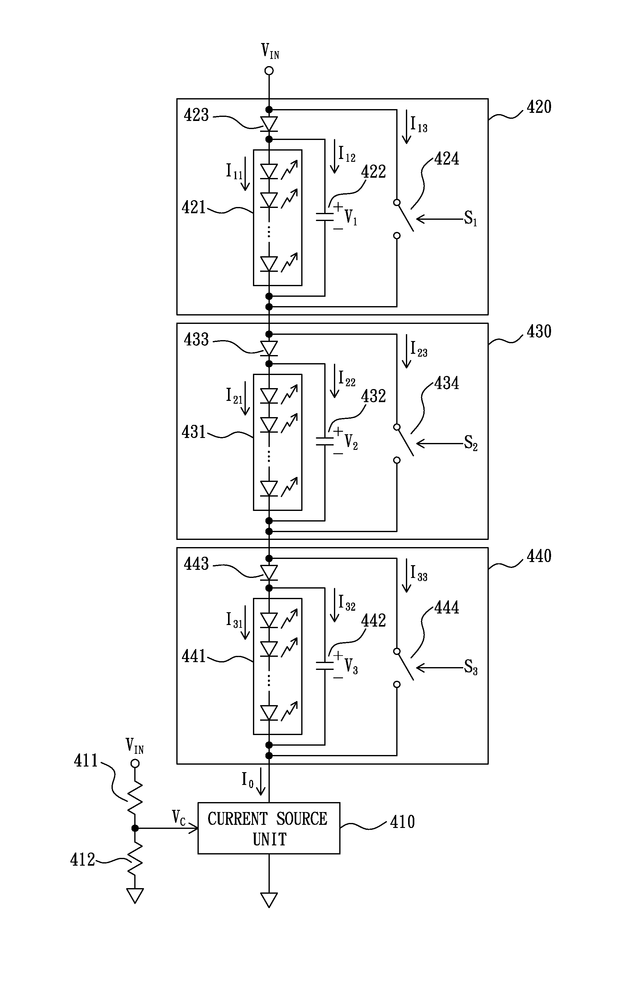
[0059]Please refer to FIG. 4, which illustrates a circuit diagram of a PFC LED driver capable of reducing current ripple according to a preferred embodiment of the present invention. As illustrated in FIG. 4, the PFC LED driver capable of reducing current ripple includes a current source unit 410, resistors 411-412, and LED load units 420, 430, and 440.

[0060]The current source unit 410 has a control terminal coupled to a control voltage VC, a first channel terminal coupled to a ground, and a second channel terminal for generating an output current IO according to the control voltage VC. The resistors 411 and 412 are used to divide a full-wave rectified line input voltage VIN to generate the control voltage VC.

[0061]The LED load unit 420, being in series with the current source unit 410, includes an LED module 421, a...


PUM


Abstract

A PFC LED driver capable of reducing current ripple, comprising: a current source unit, having a control terminal coupled to a control voltage, which is a ratio of a full-wave rectified line input voltage, a first channel terminal coupled to a power line, and a second channel terminal used to generate an output current according to the control voltage; and at least one LED load unit, being in series with the current source unit, wherein each of the at least one LED load unit comprises: a first load, including a first parallel combination of an LED module and a capacitor, wherein the LED module has at least one light emitting diode; a diode, being in a first series combination with the first load; and a switch, being in a second parallel combination with the second series combination.

Description

BACKGROUND OF THE INVENTION[0001]1. Field of the Invention[0002]The present invention relates to a PFC (power factor correction) LED (light emitting diode) driver, especially to a PFC LED driver capable of reducing current ripple.[0003]2. Description of the Related Art[0004]For general linear LED drivers, inferior efficiencies are their major disadvantages. Common solutions for improving efficiencies are to divide a string of LEDs into several sections, and select one section or multiple sections thereof to act as a load according to the voltage of a full-wave rectified line input voltage.[0005]FIG. 1 illustrates a circuit diagram of a prior art PFC LED driver. As illustrated in FIG. 1, the prior art PFC LED driver includes an amplifier 110, resistors 111-113, an NMOS transistor 114, LED modules 120, 130, and 140, and switches 121, 131, and 141.[0006]The amplifier 110 has a positive input coupled to a control voltage VC, a negative input coupled to the resistor 113, and an output co...

Claims


Application Information

Patent Timeline
Patent Type & Authority Applications(United States)
IPC IPC(8): H05B37/00
CPCH05B45/48
Inventor WANG, YEN-HUI
Owner WANG YEN HUI
Why Eureka
Try Eureka