Constant voltage welder capacitor ripple current reduction method and system

a constant voltage welder and capacitor technology, applied in the field of constant voltage welder capacitor ripple current reduction method and system, can solve the problems of increasing the cost, size, complexity, and cost of the welding system, and capacitors may generate a substantial amount of heat, and achieve the effect of reducing ripple current and reducing heating in the output capacitive circui

Active Publication Date: 2009-08-13
ILLINOIS TOOL WORKS INC
View PDF17 Cites 19 Cited by
  • Summary
  • Abstract
  • Description
  • Claims
  • Application Information

AI Technical Summary

Benefits of technology

[0003]Embodiments of the present invention provide an improved welding system utilizing a novel power conditioning circuit configured to reduce ripple current in the output capacitor. The power conditioning circuitry is designed to replace existing power conditioning circuitry used in existing welding systems, with little or no change to the other components of the systems, making it ideal for integration into existing system designs. The power conditioning circuit, in certain embodiments, includes an inductor to limit current through a capacitor, wherein the capacitor is configured to smooth the output voltage for a constant voltage welding system. The power conditioning circuit may be coupled to the output of a power supply, which may include a rectifier configured to convert AC power to DC power. The rectifier may be coupled to a DC bus configured to transmit the DC power. A capacitive circuit including a capacitor may be coupled across the DC bus to smooth ripple in the DC power. The first inductor, e.g., coupled between the DC bus and the capacitive circuit, limits the rate of change of current flow between the capacitive circuit and the DC bus during a welding operation, thereby reducing heating in the output capacitive circuit. A further inductor may be coupled to one side of the DC bus to limit the rate of change of current flow from the capacitive circuit to a load.

Problems solved by technology

In higher power welding systems, a single capacitor may be insufficient to smooth the output voltage because the capacitor does not have any limitation on current other than its own equivalent series resistance (ESR).
As a result, the capacitor may generate a substantial amount of heat as it charges and discharges during the welding process.
Unfortunately, the bank of capacitors adds to the cost, size, and complexity of the welding system.

Method used


Image

  • Constant voltage welder capacitor ripple current reduction method and system
  • Constant voltage welder capacitor ripple current reduction method and system
  • Constant voltage welder capacitor ripple current reduction method and system

Examples


Embodiment Construction

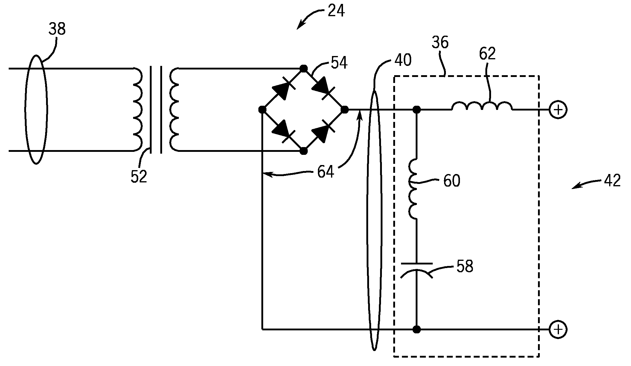
[0010]Welding systems generally apply electrical current to an electrode so as to pass an arc between the electrode and a work piece, thereby heating the electrode and work piece to create a weld. Gas metal arc welding (GMAW), also referred to by its subtypes metal inert gas (MIG) welding or metal active gas (MAG) welding, is an arc welding process in which a continuous and consumable wire electrode and a shielding gas are fed through a welding gun. Although the term welding gun is used herein, it should be understood that welding systems may also include welding torches or the like.

[0011]Most MIG welding applications operate using a constant voltage, variable current scheme to maintain a constant arc length independent of the distance between the electrode and the work piece. That is, a constant voltage regime may be implemented in which the output voltage is constant or nearly constant during welding operations. As a result, any change in arc length, which is directly related to v...


PUM

PropertyMeasurementUnit
capacitanceaaaaaaaaaa
voltageaaaaaaaaaa
arc voltageaaaaaaaaaa

Abstract

A power circuit, in certain embodiments, includes an inductor to limit current through a capacitor, wherein the capacitor is configured to smooth ripple for a constant voltage welding system. More specifically, the power circuit may include a rectifier configured to convert AC power to DC power. The rectifier may be coupled to a DC bus configured to transmit the DC power. A capacitive circuit having the capacitor may be coupled across the DC bus to smooth ripple in the DC power. The inductor, e.g., coupled between the DC bus and the capacitive circuit, limits the rate of current flow between the capacitive circuit and the DC bus during a welding operation, thereby reducing heating in the output capacitive circuit. A further inductor may be coupled to one side of the DC bus to stabilize the rate of current flow from the power circuit to a load.

Description

BACKGROUND[0001]The present invention relates generally to the field of welding systems and, more particularly, to a system and method for reducing capacitor ripple current in constant voltage welders for reducing capacitor heat and improving welding operations.[0002]Welding systems, such as metal inert gas (MIG) and flux cored arc welding (FCAW) welding systems, may supply a constant voltage, variable current to a continuously fed consumable electrode being fed through a welding gun, which then creates an arc between the consumable electrode and a work piece. The power supply of the welding system may have a capacitor or a bank of capacitors to smooth the output voltage. In higher power welding systems, a single capacitor may be insufficient to smooth the output voltage because the capacitor does not have any limitation on current other than its own equivalent series resistance (ESR). As a result, the capacitor may generate a substantial amount of heat as it charges and discharges ...

Claims


Application Information

Patent Timeline
Patent Type & Authority Applications(United States)
IPC IPC(8): H02M1/14
CPCB23K9/073H02M1/14B23K9/1043B23K9/0732
Inventor SICKELS, DARRELL L.VOGEL, BERNARD J.
Owner ILLINOIS TOOL WORKS INC
Why Eureka
Try Eureka