Ripple compensation method and apparatus

a compensation method and a technology of ripple compensation, applied in the direction of process and machine control, instruments, can solve the problems of unfavorable lighting system overall energy efficiency improvement, inability to operate directly, and undesired drive current fluctuations, so as to reduce ripple

Inactive Publication Date: 2008-02-21
KONINKLIJKE PHILIPS ELECTRONICS NV
View PDF14 Cites 33 Cited by
  • Summary
  • Abstract
  • Description
  • Claims
  • Application Information

AI Technical Summary

Benefits of technology

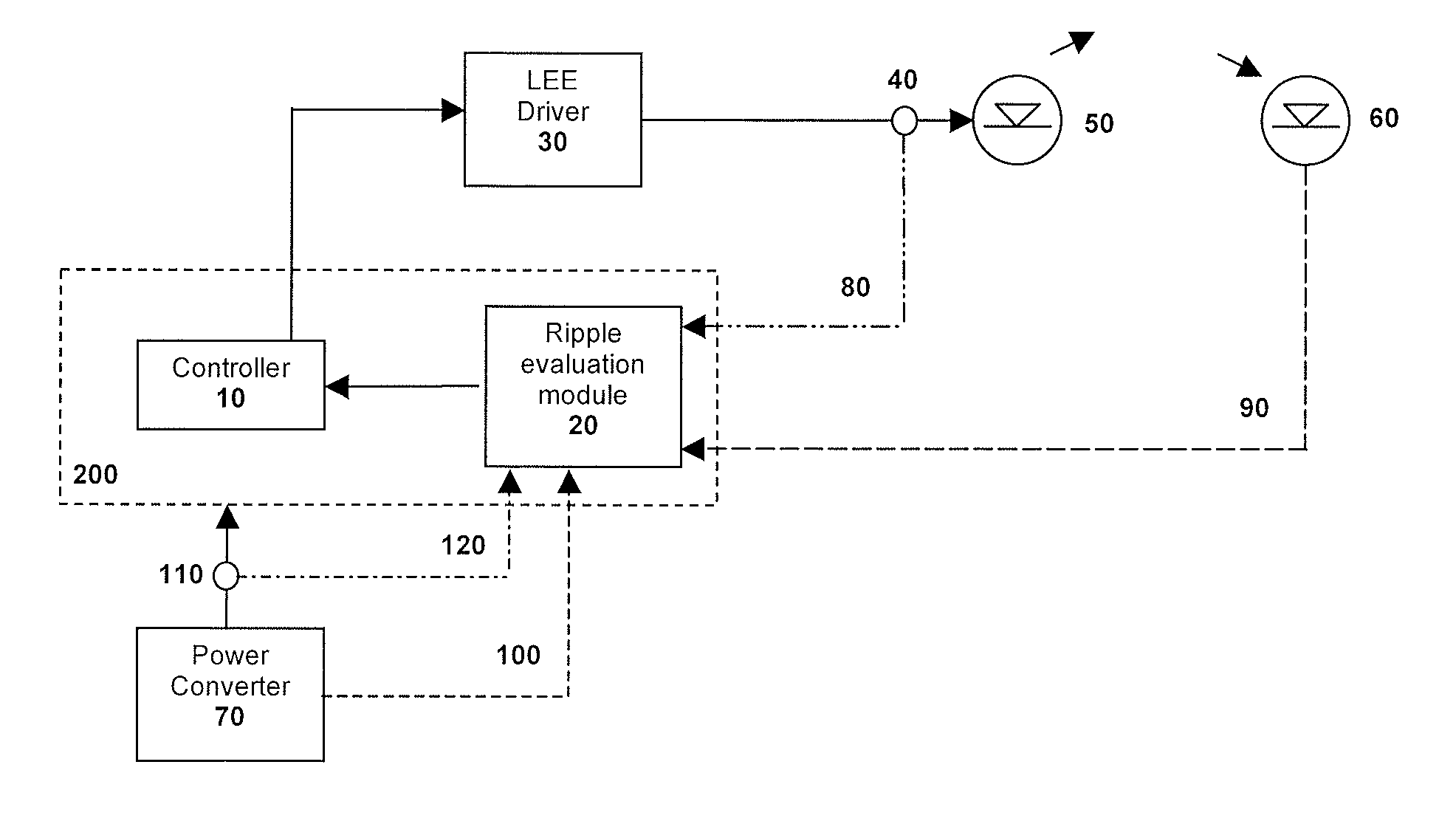
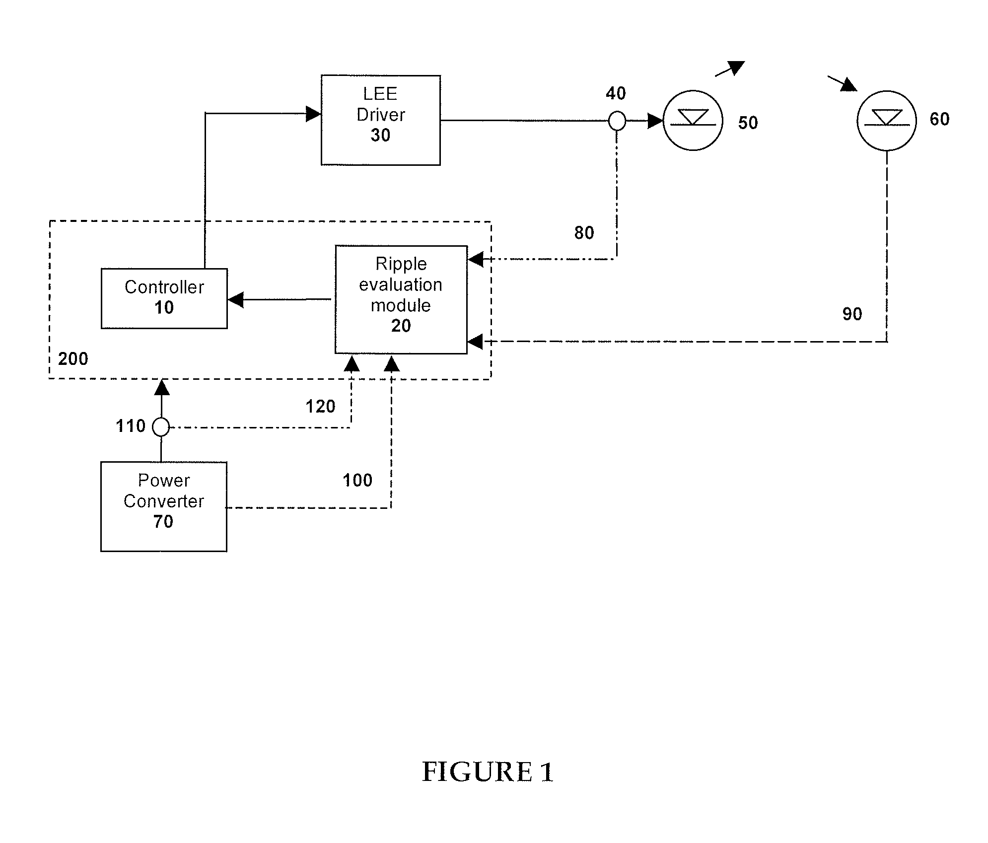
[0008]In accordance with another aspect of the invention, there is provided a method for compensating for ripple in a converter current supplied by a power converter for driving one or more light-emitting elements, the method comprising the steps of: obtaining an input indicative of the ripple present in the converter current; evaluating a ripple compensation factor based on said input; and applying said ripple compensation factor to the converter current and thereby providing a drive current for driving the one or more light-emitting elements having reduced ripple.

Problems solved by technology

Light-emitting diode based luminaries often require specific forms of electrical power and cannot be operated directly with the forms of electricity which are provided by power grids.
This excludes the use of certain types of power converters which, while possibly simple and cost effective, are prone to cause undesired drive current fluctuations.
Modular high quality power converters with, for example, drive current feedback control can significantly reduce LED flicker but generally are not able to take advantage of the unique characteristics of LEDs, are usually expensive and do not significantly improve the overall energy efficiency of the lighting system.

Method used


Image

  • Ripple compensation method and apparatus
  • Ripple compensation method and apparatus
  • Ripple compensation method and apparatus

Examples


Embodiment Construction

Definitions

[0014]The term “ripple” is used to define a form of residual harmonic content of a DC voltage or DC current signal at the output of a power converter.

[0015]The term “light-emitting element” (LEE) is used to define a device that emits radiation in a region or combination of regions of the electromagnetic spectrum for example, the visible region, infrared and / or ultraviolet region, when activated by applying a potential difference across it or passing a current through it, for example. Therefore a light-emitting element can have monochromatic, quasi-monochromatic, polychromatic or broadband spectral emission characteristics. Examples of light-emitting elements include semiconductor, organic, or polymer / polymeric light-emitting diodes, optically pumped phosphor coated light-emitting diodes, optically pumped nano-crystal light-emitting diodes or other similar devices as would be readily understood by a worker skilled in the art. Furthermore, the term light-emitting element is...


PUM


Abstract

The present invention provides a ripple compensation method and apparatus that provides a means to compensate for drive current ripple-induced brightness fluctuations in an LEE based illumination system. The ripple compensation apparatus comprises a ripple evaluation module which is configured to evaluate a ripple compensation factor based on an evaluated fluctuation of the drive current. The evaluation of the fluctuation of the drive current can be determined based on information collected during operation of the LEE based illumination system and / or based on predetermined operational characteristics of the LEE based illumination. A control system comprises the ripple evaluation module and is operatively coupled to the one or more light-emitting elements, wherein the control system is configured to determine and provide control signals for operation of the one or more light-emitting elements based on the ripple compensation factor.

Description

CROSS REFERENCE TO RELATED APPLICATIONS[0001]This application claims the benefit of U.S. Provisional Application Ser. No. 60 / 839,063, filed on Aug. 21, 2006, herein incorporated by reference in its entirety.FIELD OF THE INVENTION[0002]The present invention pertains to illumination systems and in particular it pertains to drive current ripple compensation for LED type illumination systems.BACKGROUND OF THE INVENTION[0003]Inorganic and organic semiconductor light-emitting diodes (LEDs) have been successfully used in illumination applications, including architectural, entertainment, and roadway lighting, for example. Light-emitting diode based luminaries often require specific forms of electrical power and cannot be operated directly with the forms of electricity which are provided by power grids. The amount of light emitted by LEDs depends on the LED drive current. The brightness of LEDs follows changes in the drive current in a transient fashion with delay times of typically 10−7 sec...

Claims


Application Information

Patent Timeline
Patent Type & Authority Applications(United States)
IPC IPC(8): G05F1/10H05B41/36H05B44/00
CPCH05B33/0851H05B33/0818H05B45/37H05B45/12F21W2111/02
Inventor ASHDOWN, IAN
Owner KONINKLIJKE PHILIPS ELECTRONICS NV
Why Eureka
Try Eureka