Switching regulator

Inactive Publication Date: 2009-12-31
RICOH ELECTRONIC DEVICES CO LTD
View PDF6 Cites 29 Cited by
  • Summary
  • Abstract
  • Description
  • Claims
  • Application Information

AI Technical Summary

Benefits of technology

[0012]According to one embodiment of the present invention, a switching regulator is provided, which is capable of switching between PWM control and VFM control accordin

Problems solved by technology

However, the problem with such a DC-DC converter is that the timing of turning on the switch element, i.e., the timing of switching to VFM control, is determined based on an error voltage obtained by amplifying the voltage difference between the division voltage and the reference voltage, and also based on a previously specified reference voltage.
Accordingly,

Method used


Image

  • Switching regulator
  • Switching regulator
  • Switching regulator

Examples


Example

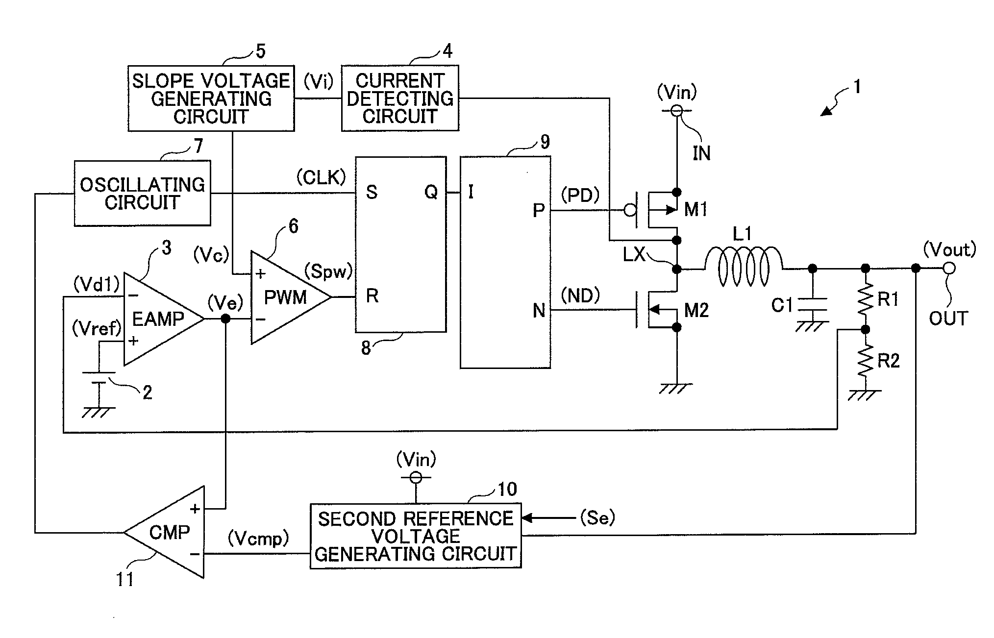
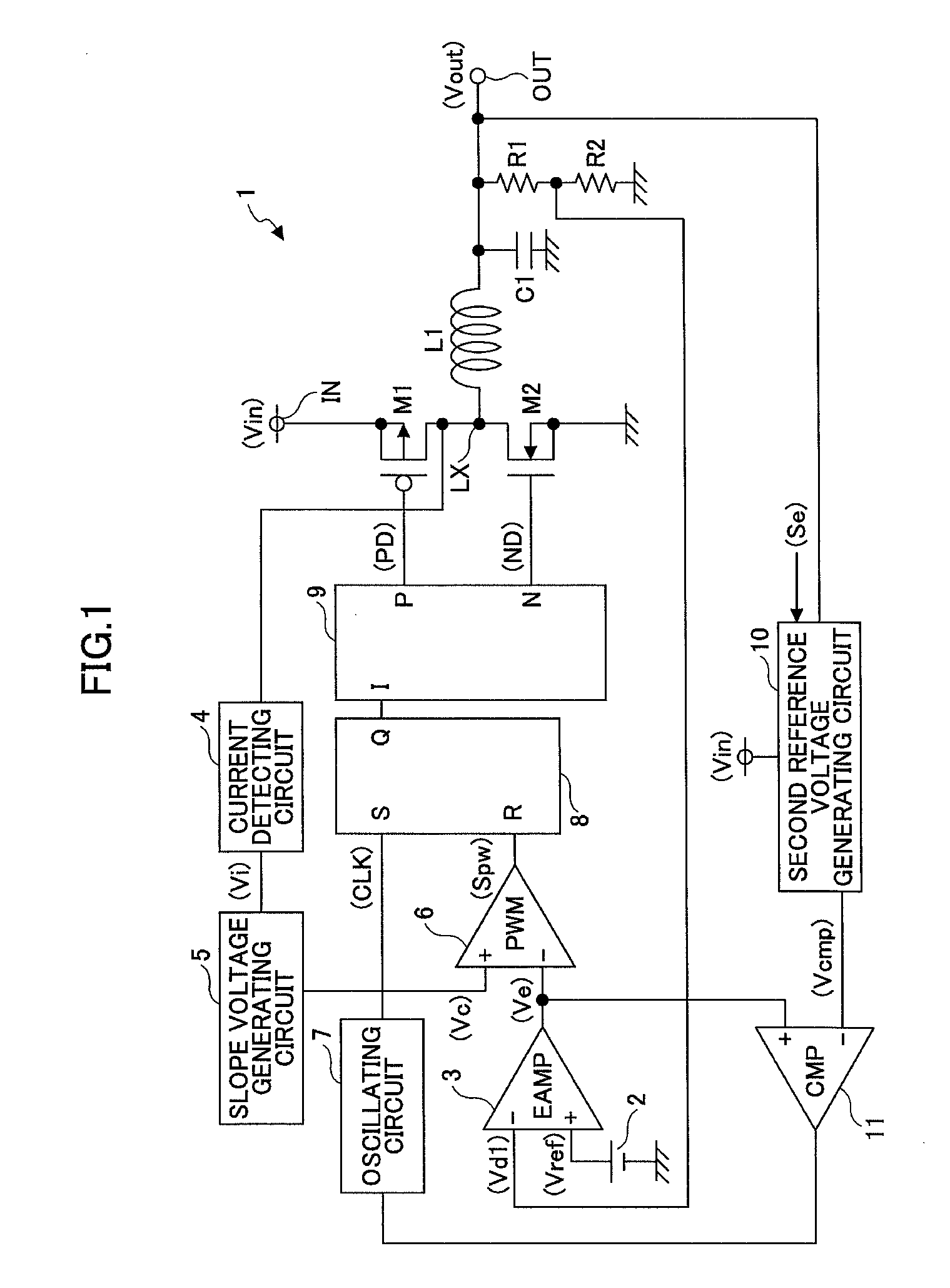
[0017]FIG. 1 illustrates a circuit example of a switching regulator according to a first embodiment of the present invention.

[0018]A switching regulator 1 constitutes a step-down type switching regulator, in which the current mode can be controlled, for stepping down an input voltage Vin input to an input terminal IN to a predetermined constant voltage, and outputting the voltage as an output voltage Vout from an output terminal OUT.

[0019]The switching regulator 1 includes a switching transistor M1 constituting a PMOS transistor that performs a switching operation for controlling the output of the input voltage Vin; a synchronous rectification transistor M2 constituting an NMOS transistor; an inductor L1; an output capacitor C1; and resistors R1 and R2 used for detecting the output voltage, and generating and outputting a division voltage Vd1 obtained by dividing the output voltage Vout. Furthermore, the switching regulator 1 includes a first reference voltage generating circuit 2 f...


PUM


Abstract

In a switching regulator, when a control switching signal received from outside is indicating PWM control, a second reference voltage generating circuit outputs, as a second reference voltage, a voltage that is lower than the minimum voltage of an output voltage range of an error amplifying circuit, so that output signals from a comparator are fixed at a high level. When a control switching signal received from outside is indicating VFM control, the second reference voltage generating circuit adjusts the second reference voltage according to the voltage difference between an input voltage and an output voltage, because the optimum second reference voltage varies according to the voltage difference between the input voltage and the output voltage.

Description

BACKGROUND OF THE INVENTION[0001]1. Field of the Invention[0002]The present invention relates to a switching regulator capable of preventing variations in the output voltage and operating by consuming low power, under light load conditions.[0003]2. Description of the Related Art[0004]A conventional switching regulator performs PWM (Pulse Width Modulation) control under regular conditions, and switches to performing VFM (Variable Frequency Modulation) control under light load conditions.[0005]With PWM control, the constant voltage output operation is performed by fixing the frame frequency and feeding back a monitored output status to adjust the time during which a switch element is turned on in accordance with the fed-back status. Meanwhile, in VFM control, the constant voltage output operation is performed by fixing the time during which the switch element is turned on, or fixing the minimum time during which the switch element is turned on, and feeding back a monitored output stat...

Claims


Application Information

Patent Timeline
IPC IPC(8): G05F1/10
CPCH02M2001/0025H02M3/156H02M1/0025
Inventor HIRATA, YASUSHISAKAI, YOHICHI
Owner RICOH ELECTRONIC DEVICES CO LTD
Why Eureka
Try Eureka