Plasma treatment equipment

Active Publication Date: 2013-08-08
NAT INST OF ADVANCED IND SCI & TECH
View PDF13 Cites 16 Cited by
  • Summary
  • Abstract
  • Description
  • Claims
  • Application Information

AI Technical Summary

Benefits of technology

[0038]Since the plasma treatment equipment of the present invention has the configuration as described above, there is provided a medical and non-medical plasma treatment equipment to be used in industrial field, agricultural field, livestock industry field, forest industry field, fisheries industry, and the like, which is free from a risk of occurrence of discharge on the object to be treated from the electrode for generating plasma when starting the mild plasma treatment which does not cause a temperature increase more th

Problems solved by technology

However, this device is configured to pass an electric current to human bodies and hence trigger thermocoagulation caused by resistance heating, generate high energy, and hence may cause tissue damage depending on the usage.
In addition, since a discharge path moves to an area having less electrical resistance, the device has various drawbacks in operability.
Therefore, even though continuous treatment is intended for the purpose of reliable hemostasis, such continuous treatment is difficult due to an increase in electrical resistance caused by the thermocoagulation.
Accordingly, there are problems in both aspects of safety for tissues of human bodies and operability in treatment work.
However, this device has a relatively large treatment surface, and hence there is a problem in operability.
In addition, since a human body or an object to be treated are served as grounding electrode and discharge electricity in the atmosphere, so that there is a problem that the electric current tends to flow through the human body or the object to be treated, and a streamer discharge tends to occur.
When the streamer discharge occurs, part of the human body or the object to be treated may be damaged.
However, this device has an internal electrode facing the treated substance, there is a problem that the electric field intensity with respect to the treated substance is increased and hence an electric current becomes large, so that the delicate treated substance may be damaged.
However, this device has an internal electrode covered with a dielectric material facing the treated substance, there is a case where the electric field intensity with respect to the treated substance is increased, and hence an electric current becomes large, so that the delicate treated substance may be damaged.
In addition, a gas diffusion panel

Method used


Image

  • Plasma treatment equipment
  • Plasma treatment equipment
  • Plasma treatment equipment

Examples


example 1

[0050]The present invention will be described below in detail on the basis of Examples.

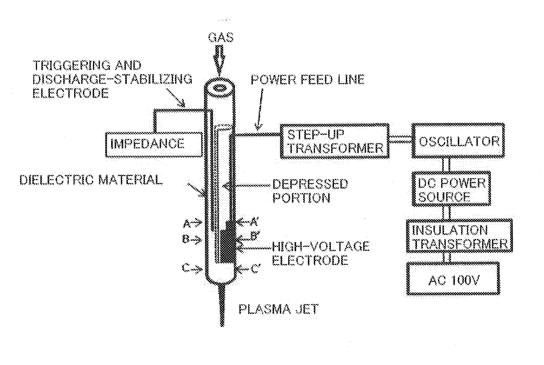
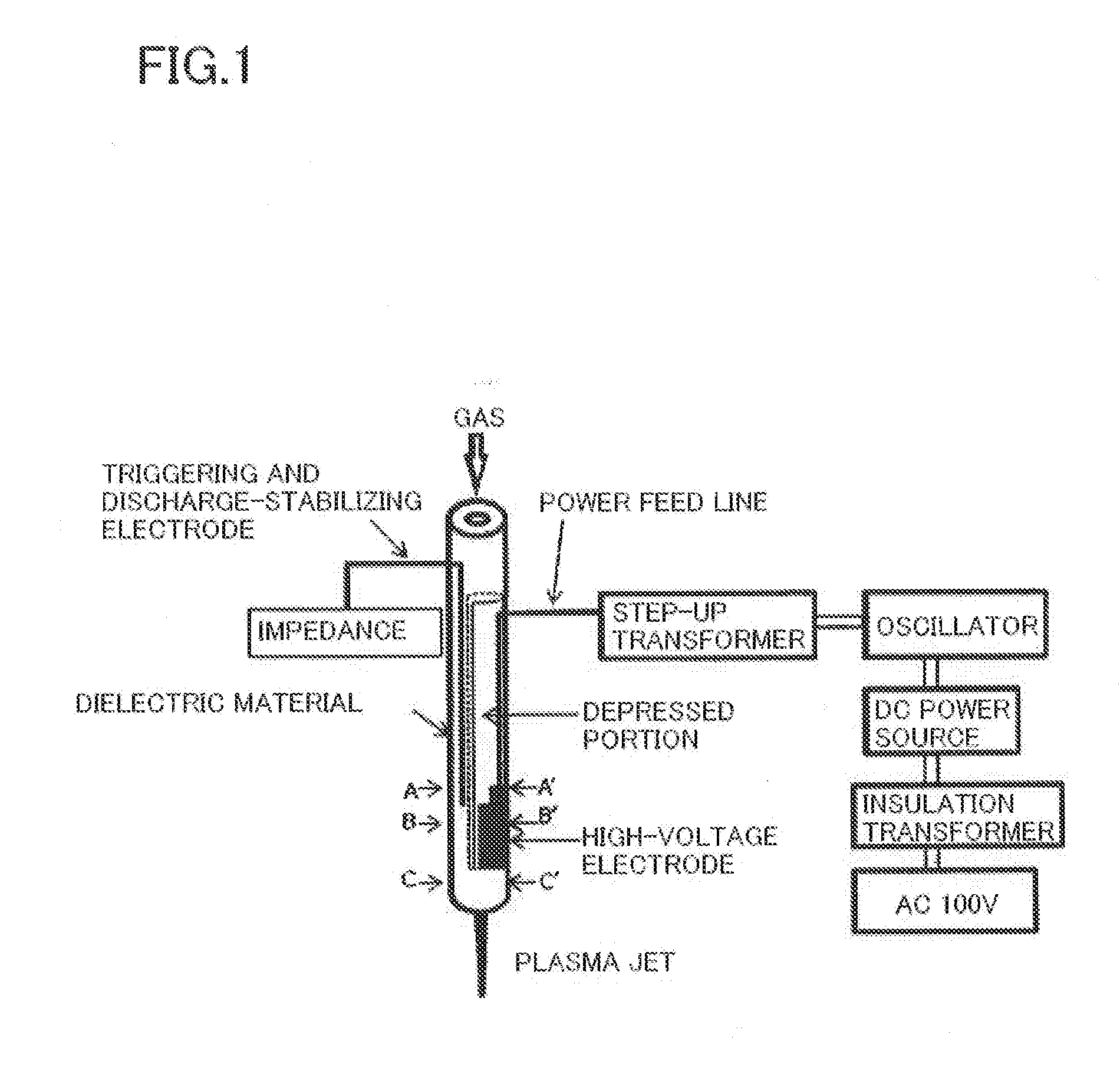
[0051]FIG. 1 is a drawing of Example 1 which is an example of the present invention. As illustrated in FIG. 1, a copper wire or the like as the triggering and discharge-stabilizing electrode is inserted into the dielectric material such as quartz. To the electrode, discharge is performed to a space via impedance (earth capacity or the like) or is grounded. A high-voltage electrode to which a voltage is applied is provided in a depressed portion having a depression deeper than the thickness of the high-voltage electrode on the dielectric material described above in closely contact therewith from the outside. The frequency of AC voltage to be applied from a power source via a power feed line is, for example, 60 kHz, and peak-to-peak voltage of the applied voltage is on the order of 7.5 kV or so. In the drawing, a power source system is composed of a commercial power source, an insulation transformer...

example 2

[0059]FIG. 3 is a plasma treatment equipment provided with a shield member as preventing leakage of high-frequency electric field on an outer surface of a dielectric material as a plasma ejection port of the plasma treatment equipment of the present invention described in FIG. 1 or FIG. 2. The shield member is let out to a space via impedance (earth capacity or the like) or grounded. Although the shield member is a copper wire coated with an insulating material such as vinyl in FIG. 3, a copper wire which is not coated is also applicable. The zero-potential side of the power source output may be grounded. In the medical application, the first priority is safety of human being as the object to be treated. Therefore, Example 2 is a configuration in which exposure to the high-frequency electric field is prevented, and a significant effect is expected for advanced control of excessive plasma treatment.

example 3

[0060]FIG. 4 is a plasma treatment equipment characterized in that the outside of the treatment device is covered with a dielectric cover as an insulating material in the plasma treatment equipment of the present invention illustrated in FIG. 1, FIG. 2, or FIG. 3. This Example has a configuration in which safety of the operator side who executes the treatment is enhanced either in medical field or industrial field.


PUM


Abstract

A plasma treatment equipment includes: a plasma starting and stabilizing unit (A) having an insulating material such as a dielectric material having an elongated hole connecting to a plasma ejection portion, a triggering and discharge-stabilizing electrode, and an intense electric field electrode mounted thereon; and a plasma generating unit (B) including the insulating material having the elongated hole and a plasma generating electrode configured to perform main plasma generation at the time of operation, wherein the triggering and discharge-stabilizing electrode, the intense electric field electrode, and the plasma generating electrode are provided in such a manner that all the electrodes are not exposed and covered with the dielectric material for the entire space of one or more of the elongated hole which allows passage of gas from the upstream, starting of the plasma and generation of the plasma, and ejection of the plasma jet.

Description

TECHNICAL FIELD[0001]The present invention relates to a plasma treatment equipment.BACKGROUND ART[0002]In recent years, aiming to treatment to various materials or medical applications or the like, studies relative to the use of plasma generated by devices on the basis of various discharging principles under atmospheric pressure environment have been conducted.[0003]Non-Patent Document 1 discloses a conventional arc-discharge type endoscope-mounted plasma device using an RF power source which was developed for medical use. However, this device is configured to pass an electric current to human bodies and hence trigger thermocoagulation caused by resistance heating, generate high energy, and hence may cause tissue damage depending on the usage. In addition, since a discharge path moves to an area having less electrical resistance, the device has various drawbacks in operability. Therefore, even though continuous treatment is intended for the purpose of reliable hemostasis, such conti...

Claims


Application Information

Patent Timeline
IPC IPC(8): H05H1/24A61B18/04
CPCA61B18/042H05H1/2406H05H2001/2412A61B2018/00982H05H1/24A61B2018/00589H05H2001/245H05H1/245
Inventor SAKAKITA, HAJIMEIKEHARA, YUZURUKIYAMA, SATORU
Owner NAT INST OF ADVANCED IND SCI & TECH
Why Eureka
Try Eureka