Method for the linear separation and connection of two elements

a technology of linear separation and connection, applied in the field of linear separation, can solve the problems of significant impact, damage to the useful load of the launcher, and significant impact in the structur

Inactive Publication Date: 2018-09-06
ARIANEGRP SAS
View PDF2 Cites 3 Cited by
  • Summary
  • Abstract
  • Description
  • Claims
  • Application Information

AI Technical Summary

Benefits of technology

The invention relates to a method, device, and launcher for securely connecting and disconnecting two elements in a safe and efficient way. The method involves using a mixture of thermite and intermetallic composition that can be triggered remotely to quickly and partially warm up the connection and cause the elements to separate. The device includes a connecting element, a mixture of thermite and intermetallic composition placed against the connecting element, and means for remotely triggering the mixture. The launcher includes a central propeller and a stage secured to the propeller, with a cutting ring for safely cutting the connection. The technical effects of this invention include improved safety, reliability, and efficiency in the connection and disconnection of elements.

Problems solved by technology

1) connections by bolting, riveting and pyrotechnical cutting by local melting of the structure. These systems, by their functioning, create debris from ejected material. In addition, the cutting causes a significant impact in the structure, which can be damaging for useful loads of the launcher;
This solution is the most used and does not create any debris, but causes a very significant impact;
This type of solution creates a lot less impacts than the two preceding solutions, but requires several bolts to transmit the stresses from one element to the other, therefore implying increased risks of failure because of the number of devices involved;
This type of solution does not allow large stresses to be transmitted between the two elements and does not enable too large diameters for the launchers.
In this case also, loosening the constraints causes a significant impact in the structures.

Method used


Image

  • Method for the linear separation and connection of two elements
  • Method for the linear separation and connection of two elements
  • Method for the linear separation and connection of two elements

Examples


Embodiment Construction

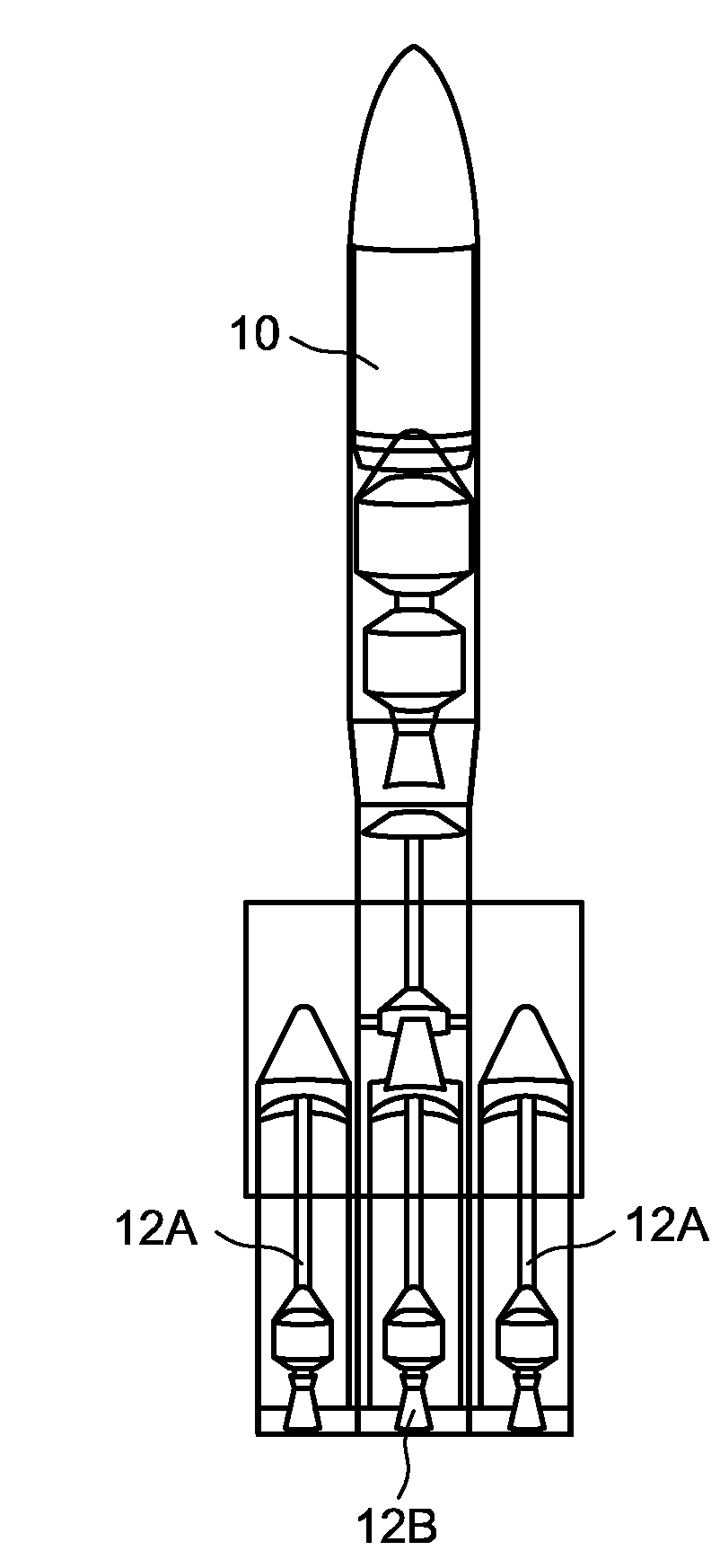
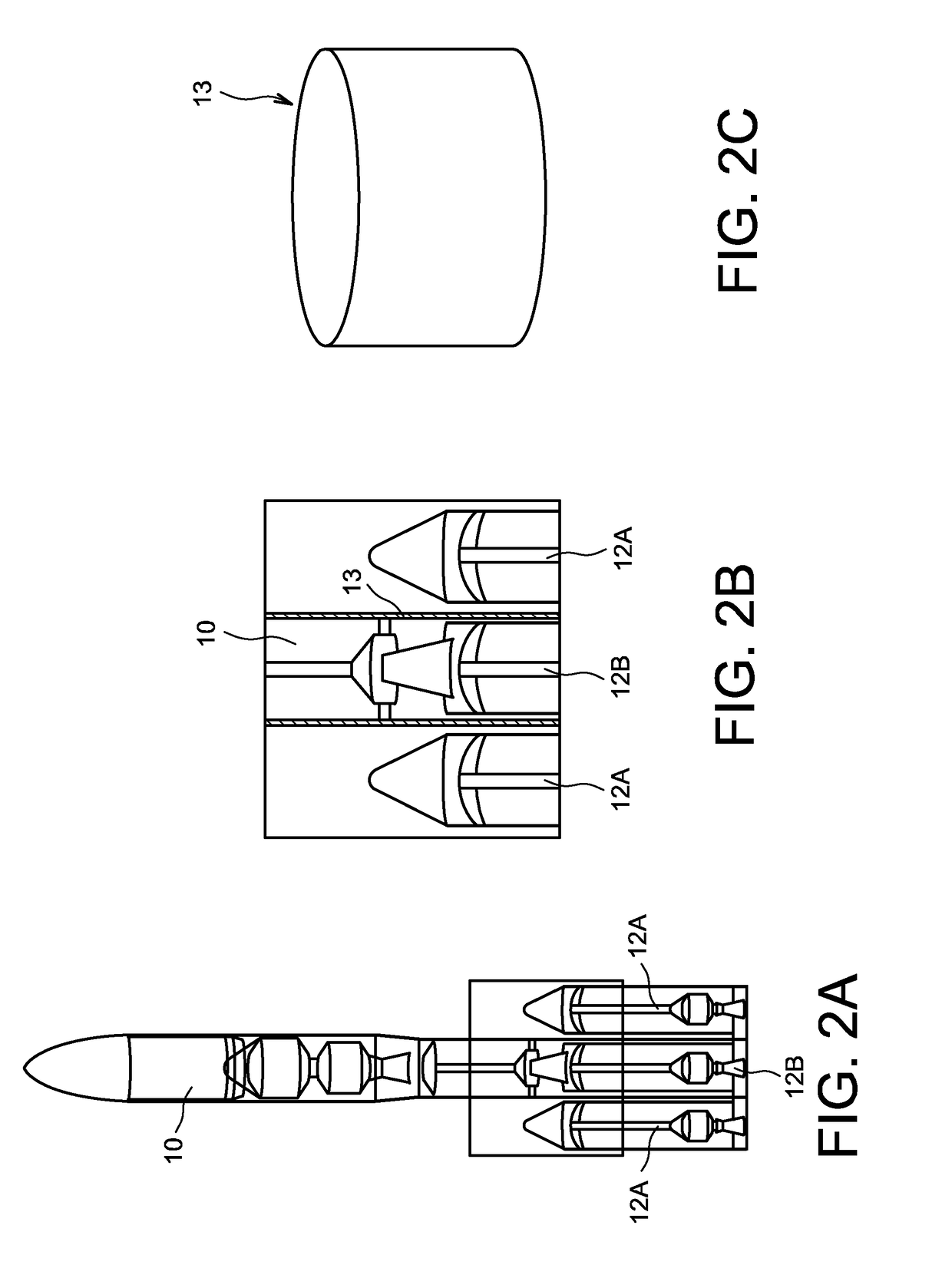
[0037]FIG. 2A represents the stages 10 of an aeronautical launcher, equipped with several propellers 12A and 12B, placed at the base of the stages 10 of the aeronautical launcher.

[0038]FIG. 2B shows a detail of this assembly, in particular, at the level of the upper part of the propellers 12A and 12B. Indeed, it can be seen that the central propeller 12B is surmounted by the stages 10. The connection is made by a connecting element 13, which is represented separate in FIG. 2C.

[0039]The device according to the invention, as well as the implementation method, are illustrated in FIG. 3A, in a detailed cross-section, at the level of the connecting element 13. This comprises, on the inner wall 14 thereof, a cutting ring 20. The latter is mainly constituted of a body 21, toroidal and open on the side of the outer diameter thereof. It is filled with a pyrogenic, energetic or thermite material 22. It is specified that by the term thermite, nanothermites are also covered.

[0040]In reference t...


PUM


Abstract

The invention relates to a method and a device allowing the separation of two stages of an aeronautical vehicle, without affecting the structure of the two stages. The device consists mainly of a connecting ring (13) secured to the two stages of the aeronautical vehicle and comprising a cutting ring (20) on the inner surface (13A) thereof, which contains a mixture of thermite and an intermetallic composition. The triggering of the latter allows the heating and melting of part of the ring (13), which separates into two parts. The invention can be applied to an aeronautical launcher.

Description

FIELD OF THE INVENTION[0001]The invention relates to a linear separation, as smooth as possible, of a first element in relation to a second element, which are previously connected rigidly. The invention applies, preferably, to space launchers, for separating stages from each other or a stage from a useful load, to missiles, space probes, even to aircraft where dropping a useful load is involved. This separation aims to reduce the mass of the boarded assembly, or to drop a useful load. These applications are characterised by the fact that it is needed to separate objects which can be fragile, for example, a satellite, and of which the connection has had to undergo high mechanical loads, like those undergone during the propulsion by a launcher.PRIOR ART AND PROBLEM RAISED[0002]FIGS. 1A and 1B illustrate this principle of separation between two elements 1 and 2 of a launcher. The first element 1 is, preferably, an element of row n, preferably, a first engine stage. The second element i...

Claims


Application Information

Patent Timeline
Patent Type & Authority Applications(United States)
IPC IPC(8): B64D1/02B64G1/64
CPCB64D1/02B64G1/645F42B15/38B64G1/6455
Inventor MEDINA, FELIPE
Owner ARIANEGRP SAS
Why Eureka
Try Eureka