Fluid mixer tap or valve

Inactive Publication Date: 2018-09-13
BINAY KUMAR BINAY KUMAR
View PDF35 Cites 3 Cited by
  • Summary
  • Abstract
  • Description
  • Claims
  • Application Information

AI Technical Summary

Benefits of technology

[0044]The other advantages of present inventions FMT are ease of its installation to a washbasin or kitchen sinks or bathtubs or any other such system using a simple back nut N1 as in first, third, fourth, sixth and eleventh embodiments of the present invention, using simple hose connectors without steel armour body for hot and cold water connection innovative Toupling C or Taptee T screwed to the outer leg of the main body of first to eighth embodiments as per various drawings described in various figures and directly connected to the main body of ninth to twelfth embodiments as per drawings described in various figures, economical in cost and easy to manufacture and installed and sturdy design and can be used in sediment free water also in some embodiments and can

Problems solved by technology

Installation of these taps are difficult and needs additional non plumbing tool in addition to horse shoes washers and bolt.
Also these hose connectors can not be used properly in non metallic taps.
This is a costly affairs as cost of two taps may be higher and also there is a risk of scolding injuries due to hot water if water temperature is high.
Turning the knob or working the lever sets the flow rate by adjusting the size of an opening in the valve assembly, giving rise to choked flow through the narrow opening in the valve.
Gate valves use a metal disc the same diameter as the pipe which is screwed into place perpendicularly to the flow, cutting it off There is no resistance to flow when the tap is fully open as it is there in globe valve, but this type of tap rarely gives a perfect seal when closed.
This make them susceptible to more damage and require more maintenance.
Its cumbersome and difficult arrangement for fixing them in the sink, washbasin, bathtubs etc. make it difficult to maintain in addition to high cost.
The disadvantages with exiting mixer taps are tap body has no legs or tails as its integral part, its hi

Method used


Image

  • Fluid mixer tap or valve
  • Fluid mixer tap or valve
  • Fluid mixer tap or valve

Examples


Example

[0095]A. Main body of First Embodiment of the present invention Fluid Mixer Tap (FMT).[0096]B. Main body of Second Embodiment of the present invention Fluid Mixer Tap (FMT).[0097]D. Main body of Third Embodiment of the present invention Fluid Mixer Tap (FMT).[0098]E. Main body of Fourth Embodiment of the present invention Fluid Mixer Tap (FMT).[0099]F. Main body of Fifth Embodiment of the present invention Fluid Mixer Tap (FMT).[0100]A′. Main body of Sixth Embodiment of the present invention Fluid Mixer Tap (FMT).[0101]B′. Main body of Seventh Embodiment of the present invention Fluid Mixer Tap (FMT).[0102]G. Main body of Eighth Embodiment of the present invention Fluid Mixer Tap (FMT).[0103]H. Main body of Ninth Embodiment of the present invention Fluid Mixer Tap (FMT) is also the Ninth Embodiment of the present invention Fluid Mixer Tap (FMT) .[0104]M. Main body of Tenth Embodiment of the present invention Fluid Mixer Tap (FMT) is also the Tenth Embodiment of the present invention...

Example

B. Second Embodiment

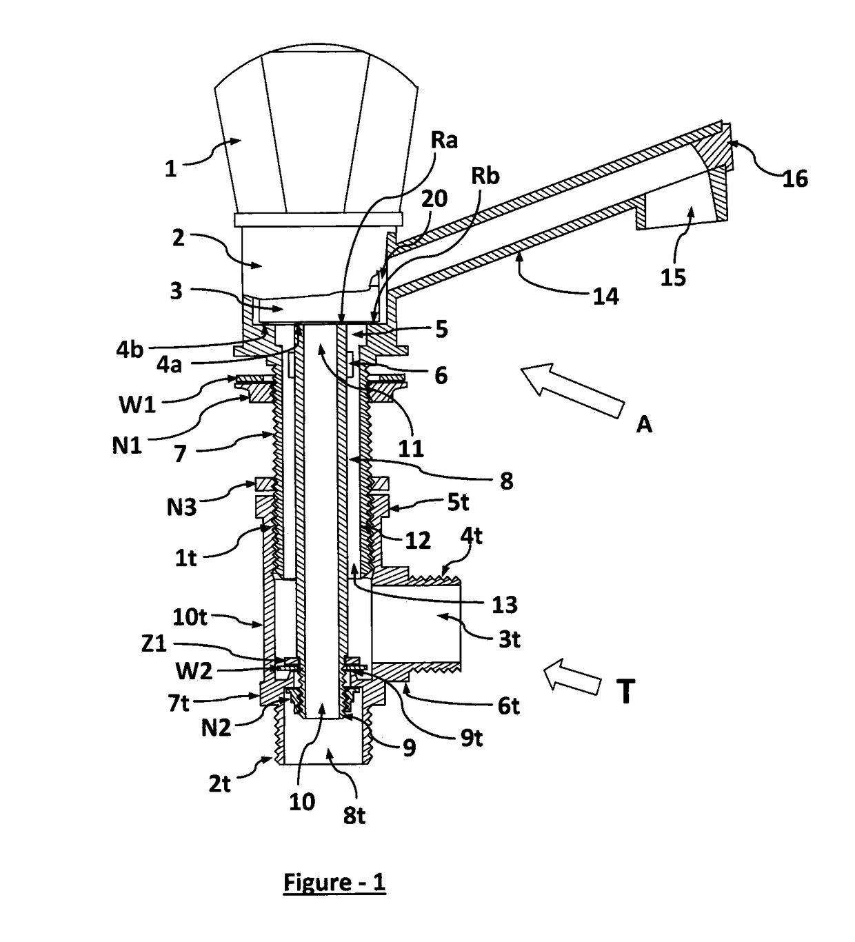
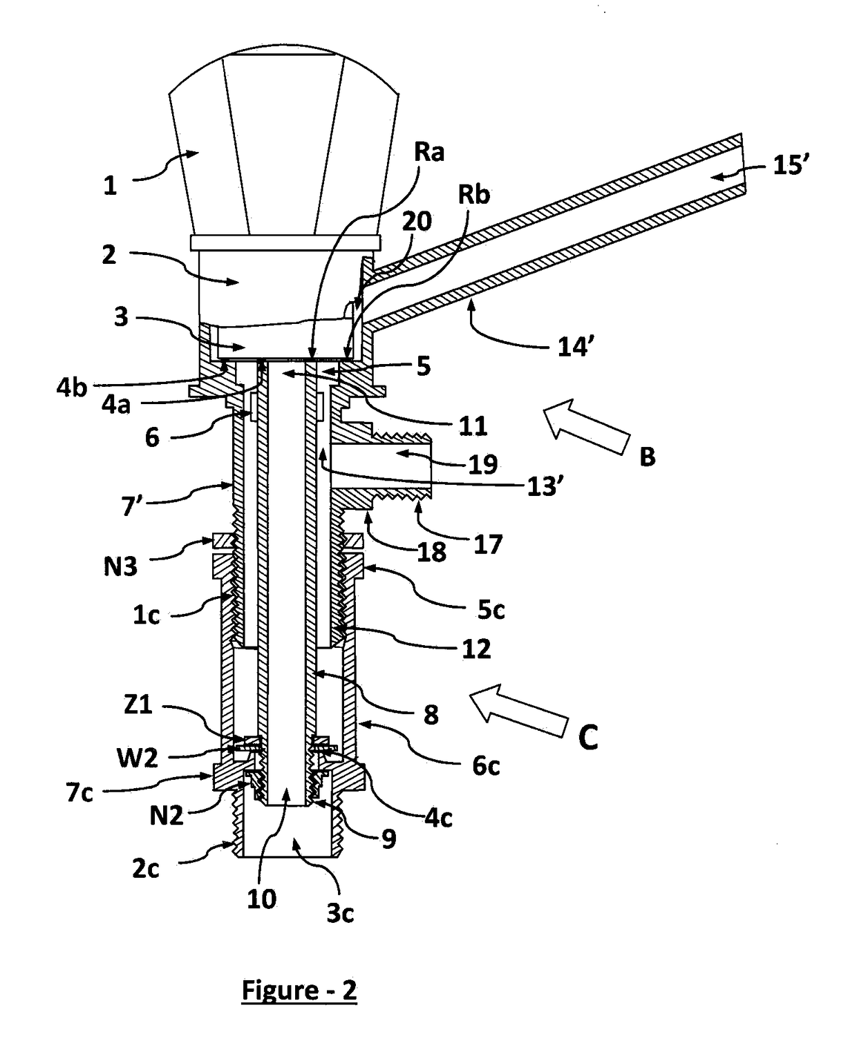
[0405]FIG. 2 describes the Second Embodiment of the present invention Fluid Mixer Taps (FMT). Partly cross sectional and partly perspective view of the second embodiment of the present invention is shown in FIG. 2.

[0406]The fluid mixer tap illustrated in FIG. 2 mainly comprises the main body B and the Toupler C screwed in the main body B.

[0407]The main body B of the second embodiment is same as that of the main body A of the first embodiment with a little difference in the outer leg 7 and the spout 14. The outer leg 7′ of the main body B is having the first leg 12 and the second leg 17. This second leg 17 is not a part of the outer leg 7 in the first embodiment of the Fluid Mixer Taps. The spout 14′ of the main body B is different from the spout 14. In this embodiment no end cap 16, securing washer W1 and back nut N1 are required as they are there in the first embodiment.

[0408]The inner leg 8 in this second embodiment is same as that in the first embodiment of th...

Example

C. Third Embodiment

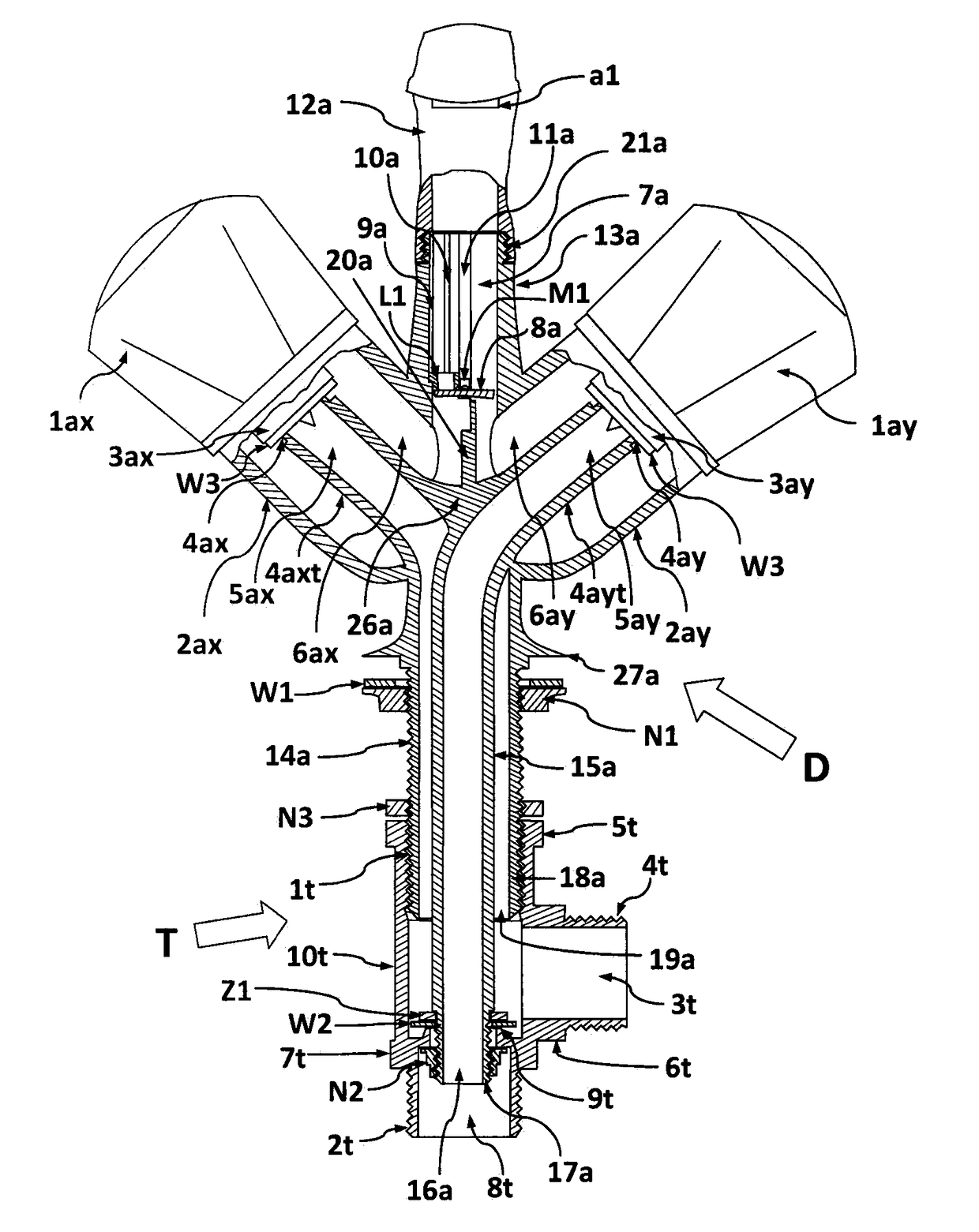
[0420]FIG. 3 describes the Third Embodiment of the present invention Fluid Mixer Tap (FMT). Partly cross sectional and partly perspective view of the Third Embodiment of the present invention FMT is shown in FIG. 3.

[0421]FIG. 4 describes the main body D of the third embodiment of the present invention Fluid Mixer Tap (FMT). Partly cross sectional and partly perspective view of the main body D is shown in FIG. 3 and FIG. 4.

[0422]The Fluid Mixer Tap (FMT) illustrated in FIG. 3 substantially comprises the main body D and the Taptee T screwed in the main body D.

[0423]The main body D substantially comprises two tap bodies 2ax and 2ay, two tap cartridges 3ax and 3ay, two tap handles 1ax and 1ay, a header 13a, an interlocking mechanism, an outlet spout 12a and two concentric tubular legs inner leg 15a and outer leg 14a. The header 13a, the two concentric legs 15a and 14a are integral parts of the tap bodies 2ax and 2ay and can be moulded or casted in a single moulding di...


PUM


Abstract

The invention relates to a water mixer tap, for mixing hot/cold fluid or water, having one tap body-cartridge-handle with plurality of concentric legs or tails connected to concentric ports in the cartridge/plurality of tap bodies-cartridges-handles with plurality of concentric or parallel legs or tails connected to individual tap bodies such that discharge of fluid or water from all tap bodies finally entered into a common header for all tap bodies for discharge of fluid in a mixer chamber in various embodiments of the present invention Fluid Mixer Tap. The tap handle rotatably mounted about a longitudinal axis with respect to the tap body and operatively connected to the tap cartridge or valve assembly such that rotating the handle to a selected position connects inner and outer port/concentric inner and outer ports to a mixing chamber in header and controls the proportions of the hot and cold water supplied from the mixing chamber from the respective hot and cold water supply lines for discharge through the spout In one preferred embodiment there is interlocking of hot and cold water line, such that hot water can entered into spout only when cold water valve is open other wise hot water will not enter the spout. In some embodiments invented tap fittings Toupling C or Taptee T are used for connecting to hot/cold inlet water supply lines where as in some other embodiment they are not used. Here the inlet legs are directly connected to pipe fittings and hose connectors. The taps are attachable to kitchen sink, bathtub or washbasin or baths in various embodiments as per design. Moreover, the inventive mixer tap can be used as a mixer tap or valve for mixing two or more type of fluids in a single unit. The use of the invention makes it possible to improve life cycle and ease of installation along with robust construction and economical cost of water mixer tap for consumer.
There are twelve embodiments and further embodiments are disclosed in the present invention Fluid Mixer Taps or Valves (FMT) which are developed for use in baths, kitchen sinks, wash area, bath tubs, industries, hospitals etc. according to respective embodiments and attachable to them for delivery of mixed water/fluids. The Fluid Mixer Taps (Valves) comprises, in the First to Eighth embodiments of the present invention, two main parts in each embodiment one is a main body and the other is either a Toupling C or a Taptee T connected to the main body as per various drawings in FIG. 1 to FIG. 11 and in the ninth to twelfth embodiments neither Toupling C nor Taptee T is required to be attached to the main body wherein there is only one body which are thought of and developed to provide mixing facility in a single body for connection to elbows or tees or any other suitable pipe fittings for cold and hot water or/and raw water separately in cases where there are two/three tap bodies and two/three input legs or tails respectively. There are plurality of legs or tails for connection to the hot water supply line and cold water supply line.

Description

2. FIELD AND BACKGROUND OF THE INVENTION[0001]The present invention Fluid Mixer Tap or Valve (FMT) relates to a water / fluid mixer tap or valve that mixes water / fluid from two or more inlet water / fluid supply lines and discharge mixed water / fluid from its outlet.[0002]Here hot and cold water / fluids or any other two or more types of fluids from two or more inlet supply lines respectively are mixed by this Fluid Mixer Tap or Valve before reaching the outlet, allowing in the case of hot and cold water supply lines to emerge water at any temperature between that of hot and cold water inlet supplies and in case of two or more type of inlet fluids, a mixer of fluids depending upon opening of individual handle for single handle disc cartridges or opening position of a number of tap handles in case of more number of tap handles in the present invention FMT.[0003]In prior arts, various types of water mixer taps are available. In one type water mixer tap uses two taps one for hot water and oth...

Claims


Application Information

Patent Timeline
IPC IPC(8): E03C1/02E03C1/04F16K11/20F16K11/00
CPCE03C1/023E03C1/0403F16K11/205F16K11/207F16K19/006E03C1/021F16K11/20
Inventor BINAY KUMAR, BINAY KUMAR
Owner BINAY KUMAR BINAY KUMAR
Why Eureka
Try Eureka