Surveillance system and surveillance device

a surveillance system and surveillance device technology, applied in the field of surveillance systems and surveillance devices, can solve the problems of difficult operation, inconvenient adjustment of lens orientation, complicated adjustment mechanism of conventional lenses,

Active Publication Date: 2018-09-27
VIVOTEK INC
View PDF0 Cites 3 Cited by
  • Summary
  • Abstract
  • Description
  • Claims
  • Application Information

AI Technical Summary

Benefits of technology

[0006]As mentioned in the above, the first support frame can move along the ring-shaped track by the first roller and the second roller, such that the lens module moves with the first support frame along the ring-shaped track. Furthermore, the second support frame can rotate with respect to the first support frame, such that the lens module rotates with the second support frame with respect to the first support frame. Moreover, the lens module can rotate with respect to the second support frame. By means of the aforesaid mechanism, a user can adjust the lens orientation conveniently and rapidly to satisfy different requirements of surveillance orientations.

Problems solved by technology

Currently, an adjusting mechanism of a conventional lens is complicated and not easy to be operated.
Accordingly, it is inconvenient to adjust the lens orientation.

Method used


Image

  • Surveillance system and surveillance device
  • Surveillance system and surveillance device
  • Surveillance system and surveillance device

Examples


Embodiment Construction

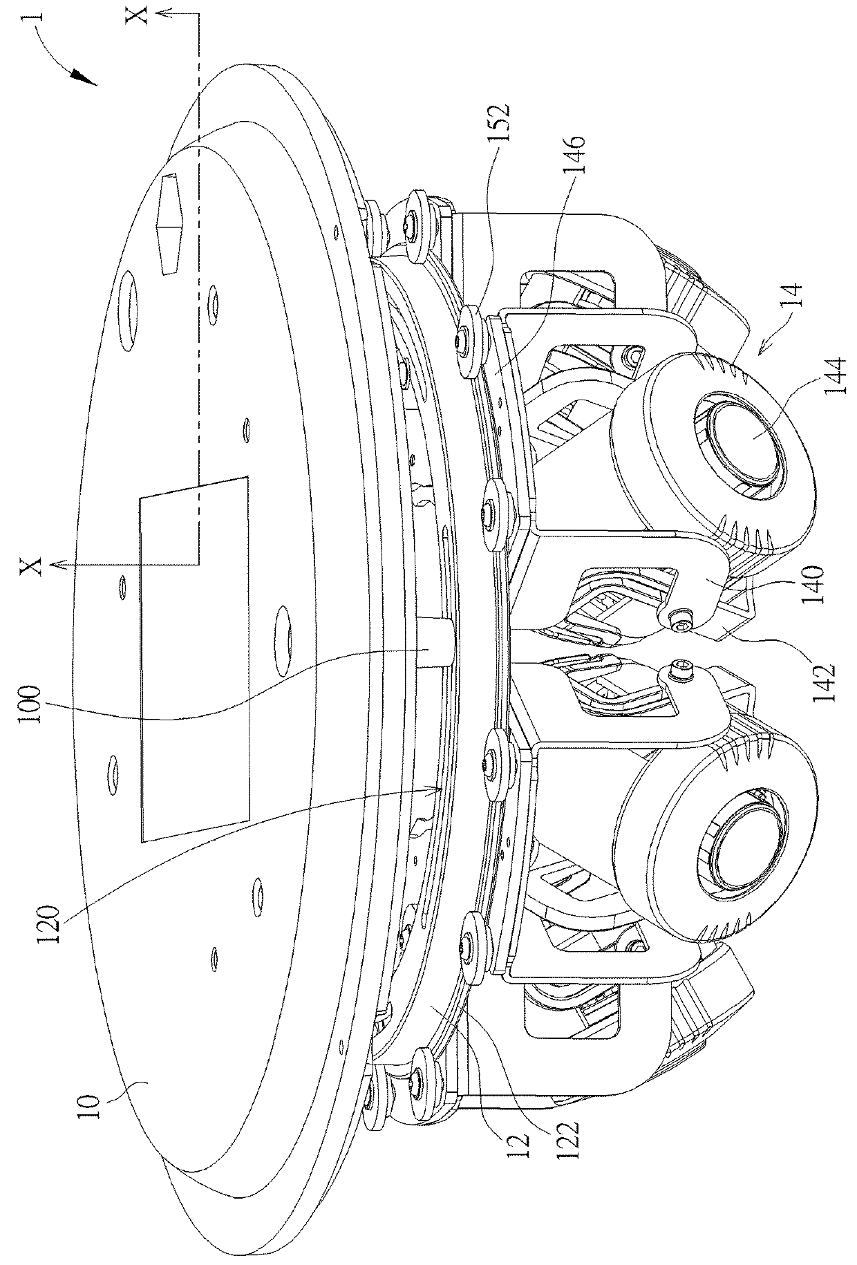
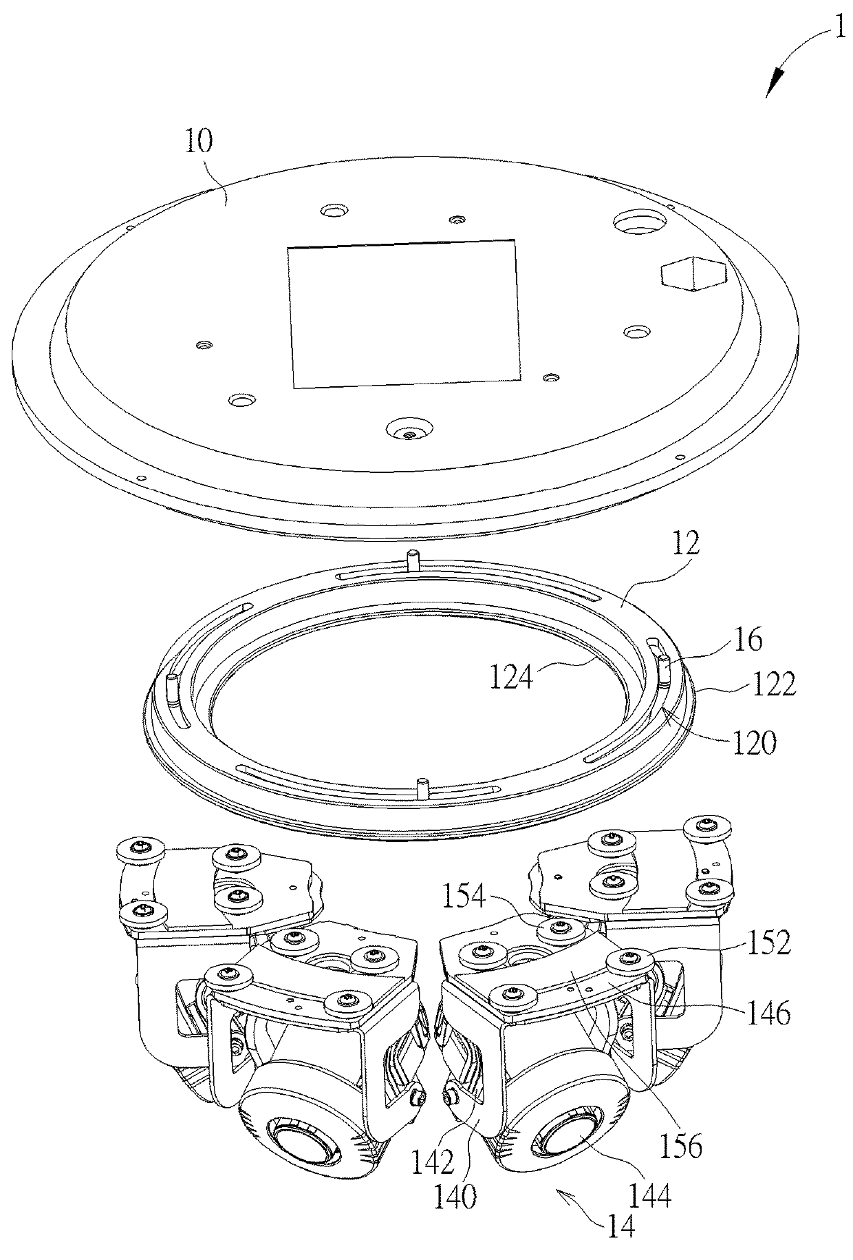
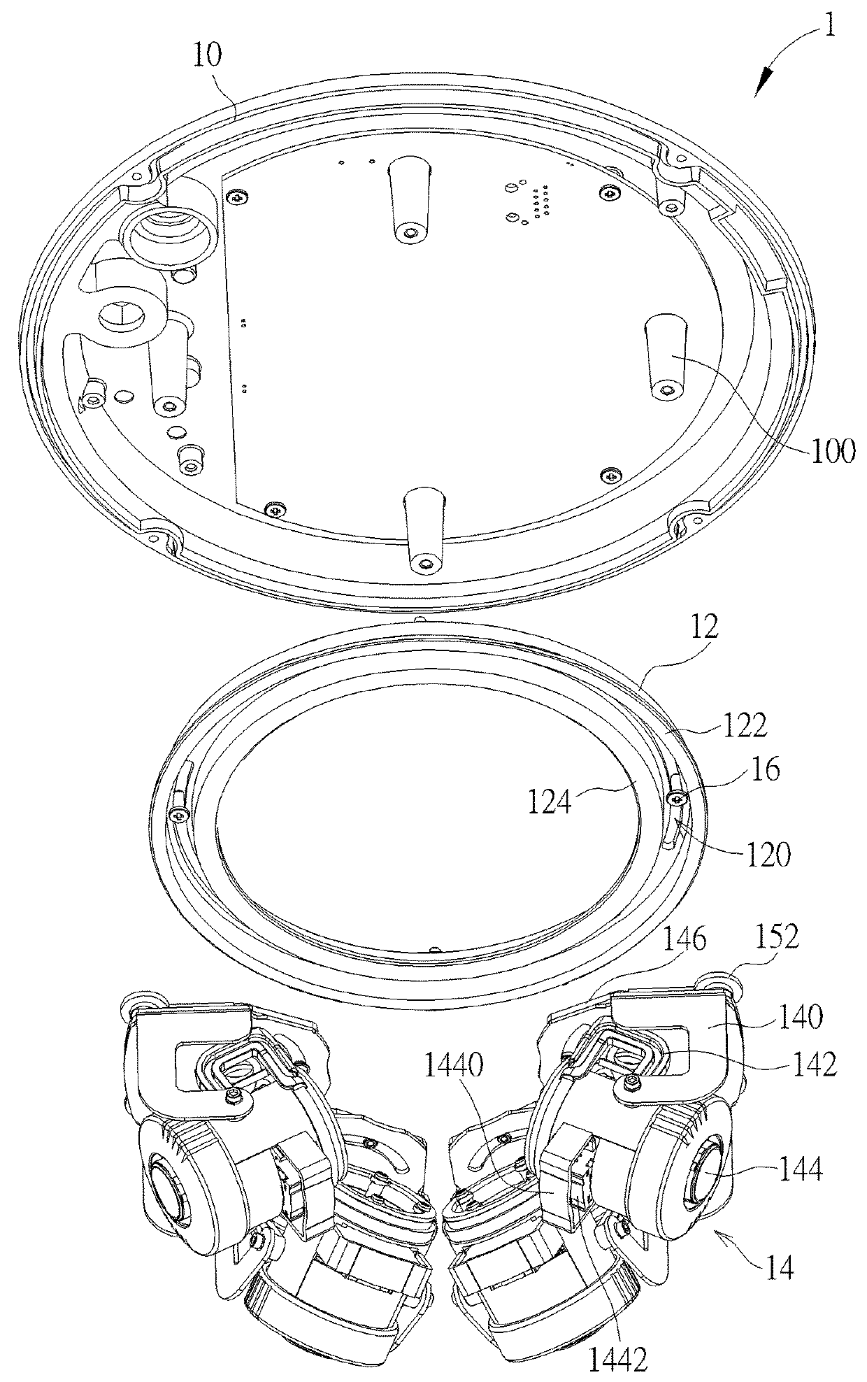
[0024]Referring to FIGS. 1 to 10, FIG. 1 is a perspective view illustrating a surveillance system 1 according to an embodiment of the invention, FIG. 2 is an exploded view illustrating the surveillance system 1 shown in FIG. 1, FIG. 3 is an exploded view illustrating the surveillance system 1 shown in FIG. 1 from another viewing angle, FIG. 4 is a sectional view illustrating parts of the surveillance system 1 along line X-X shown in FIG. 1, FIG. 5 is an assembly view illustrating the ring-shaped track 12 and the surveillance device 14 shown in FIG. 2, FIG. 6 is a perspective view illustrating the surveillance device 14 shown in FIG. 1, FIG. 7 is an exploded view illustrating the surveillance device 14 shown in FIG. 6, FIG. 8 is an exploded view illustrating the surveillance device 14 shown in FIG. 6 from another viewing angle, FIG. 9 is an assembly view illustrating the first support frame 140 and the fixing frame 146 shown in FIG. 8, and FIG. 10 is a sectional view illustrating the...


PUM


Abstract

A surveillance system includes a ring-shaped track, a first support frame, at least one first roller, at least one second roller and a lens module. The ring-shaped track has an outside flanged portion and an inside flanged portion. The at least one first roller is disposed on the first support frame and leans against the outside flanged portion. The at least one second roller is disposed on the first support frame and leans against the inside flanged portion, such that the ring-shaped track is sandwiched in between the at least one first roller and the at least one second roller. The lens module is disposed on the first support frame.

Description

BACKGROUND OF THE INVENTION1. Field of the Invention[0001]The invention relates to a surveillance system and a surveillance device and, more particularly, to a surveillance system and a surveillance device capable of adjusting a lens orientation conveniently and rapidly.2. Description of the Prior Art[0002]Since safety awareness is being raised gradually, people pay much attention to safety surveillance application. So far in many public or non-public places, there are always one or more cameras installed for safety surveillance. When a lens orientation of a camera does not coincide with a surveillance orientation desired by a user, the user has to adjust the lens orientation to coincide with the surveillance orientation. Currently, an adjusting mechanism of a conventional lens is complicated and not easy to be operated. Accordingly, it is inconvenient to adjust the lens orientation.SUMMARY OF THE INVENTION[0003]An objective of the invention is to provide a surveillance system and a...

Claims


Application Information

Patent Timeline
Patent Type & Authority Applications(United States)
IPC IPC(8): G02B7/02H04N7/18
CPCG02B7/023H04N7/181H04N23/51H04N23/57
Inventor CHENG, SZU-HSINGCHEN, CHIH-HAO
Owner VIVOTEK INC
Why Eureka
Try Eureka