Objective-type dark-field illumination device for microfluidic channel

a microfluidic channel and illumination device technology, applied in measurement devices, instruments, scientific instruments, etc., can solve the problem of not providing a suitable dark-field illumination for clearly observing, and achieve the effect of reducing image contrast, convenient and rapid adjustment, and efficiently solving problems

Inactive Publication Date: 2011-06-30
NAT SUN YAT SEN UNIV
View PDF11 Cites 22 Cited by
  • Summary
  • Abstract
  • Description
  • Claims
  • Application Information

AI Technical Summary

Benefits of technology

[0007]A primary object of the present invention is to provide an objective-type dark-field illumination device for detecting samples in a microfluidic channel, which includes: an optical stop having a pair of symmetric curved slits used to adjust the optical path and inner numerical aperture (N.A.) of a dark-field light source generated by the device; the outer N.A. is determined by the match of a high N.A. of an excited objective lens; the inner N.A. and the outer N.A. of the dark-field illumination can be adjusted to determine the path of the excitation light by the optical stop pattern. As a result, the path behavior of this invented dark-field illumination can be conveniently and rapidly adjusted for illuminating a tested sample in a microfluidic channel, while the device is advantageous to efficiently solve the problem of a traditional dark-field illumination that may generate noise scattered from inner walls of the microfluidic channel to lower the image contrast. Therefore, the signal resolution of capturing the scattered light and / or emitted fluorescence from the tested sample in the microfluidic channel during observation can be enhanced. Meanwhile, the device can simultaneously detect various fluorescent samples with different excited wavelengths in the microfluidic channel.

Problems solved by technology

As a result, the excitation spot may illuminate inner walls of the microfluidic channel to cause a large number of background noise due to the scattering of the channel wall, so that the traditional device cannot provide a suitable dark-field illumination for clearly observing the samples in the microfluidic channel.

Method used


Image

  • Objective-type dark-field illumination device for microfluidic channel
  • Objective-type dark-field illumination device for microfluidic channel
  • Objective-type dark-field illumination device for microfluidic channel

Examples


Embodiment Construction

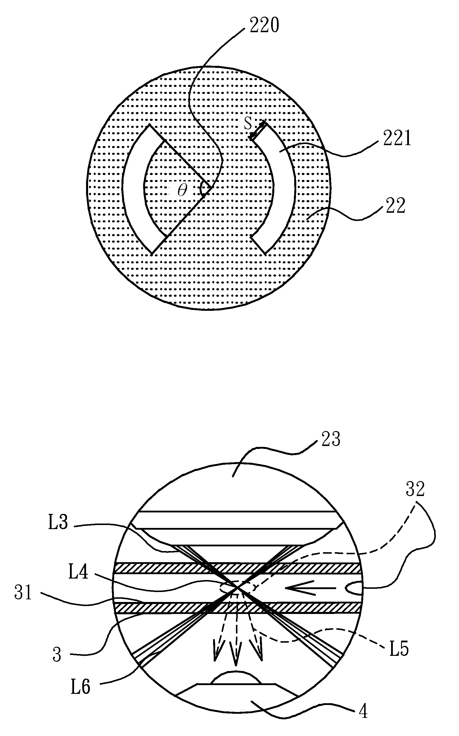
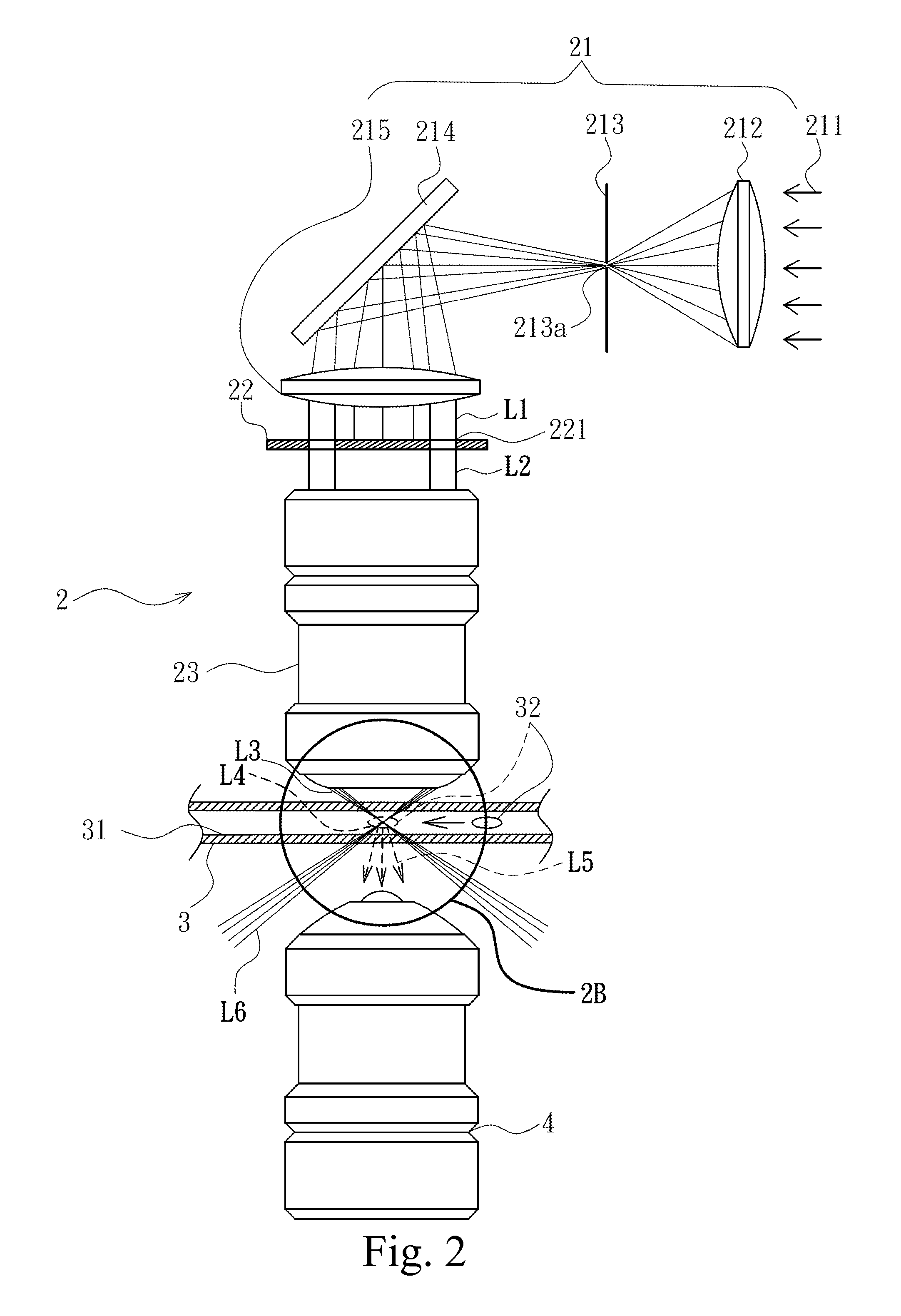
[0034]Referring now to FIGS. 2, 2A, 2B and 3, an objective-type dark-field illumination device for a microfluidic channel according to a preferred embodiment of the present invention is illustrated. As shown, an objective-type dark-field illumination device 2 is generally provided on a first side of a microfluidic chip 3, wherein the dark-field illumination device 2 comprises a parallel light source assembly 21, an optical stop 22 and a transmitter objective lens 23 with high numerical aperture (N.A.). The dark-field illumination device 2 is used to provide a suitable dark-field illumination to illuminate samples 32 in a microfluidic channel 31 of the microfluidic chip 3, so as to considerably lower background light noise scattered from inner walls of the microfluidic channel 31 for the purpose of increasing the contrast and signal / noise ratio of sample images and detection signals. In addition, a receiver objective lens 4 is provided on a second side of the microfluidic chip 3 to r...


PUM


Abstract

An objective-type dark-field illumination device for a microfluidic channel is provided and includes an optical stop having a pair of symmetric curved slits used to adjust the optical path and inner numerical aperture of a dark-field light source generated by the device. The dark-field illumination can focus on a smaller spot to illuminate a sample in the microfluidic channel by matching a pin-hole combined with a transmitter objective lens. The optical path and smaller spot is advantageous to solve the problem of a traditional dark-field illumination that may generate background light noise scattered from inner walls of the microfluidic channel to lower the image contrast. Therefore, the signal or image resolution of capturing the scattered light and/or emitted fluorescent light emitted from the sample in the microfluidic channel can be enhanced. Meanwhile, the device can simultaneously excite and detect multiple fluorescent samples with different excited wavelengths in the microfluidic channel.

Description

FIELD OF THE INVENTION[0001]The present invention relates to an objective-type dark-field illumination device for a microfluidic channel, and more particularly to an objective-type dark-field illumination device which includes an optical stop having a pair of symmetric curved slits to adjust the light path field for producing a pair of parallel light with curved profile, and combines with a transmitter objective lens to generate a dark-field illumination for illuminating a tested sample in a microfluidic channel by a smaller focused spot due to a small pin-hole.BACKGROUND OF THE INVENTION[0002]A traditional dark-field illumination system is used to observe an un-stained semi-transparent material (such as cells, micro-algae or other biological samples) in a transparent medium. The main technology of the dark-field illumination system is based on the principle that scattered and reflective light will be generated when a light passes through a sample substance, and thus the system can ...

Claims


Application Information

Patent Timeline
Patent Type & Authority Applications(United States)
IPC IPC(8): G02B21/06
CPCG01N15/1434G01N21/474G02B21/10G01N2021/4704G01N2021/6421G01N21/645G01N15/1459
Inventor LIN, CHE-HSINLIN, SHI-WEIHSU, JUI-HUNGCHANG, CHIH-HAN
Owner NAT SUN YAT SEN UNIV
Why Eureka
Try Eureka