Multifunctional fuel gas nozzle

a multi-functional, fuel gas technology, applied in the direction of burners, combustion types, combustion processes, etc., can solve the problems of difficult to distinguish the difference between the diameters of the nozzles, the nozzle cannot be changed by consumers, and the nozzle diameter is difficult to be easily adjusted by consumers, so as to simplify the nozzle structure, facilitate and rapid adjustment of the nozzle diameter, the effect of high precision

Inactive Publication Date: 2009-08-13
TSUNG KAO HSUNG
View PDF13 Cites 5 Cited by
  • Summary
  • Abstract
  • Description
  • Claims
  • Application Information

AI Technical Summary

Benefits of technology

[0026]Compared with the prior art, the core and the switch strip are mounted inside the shell, and the stopping portion is disposed at the front end of the shell according to the present invention. Such kind of structure can achieve the purpose of conveniently and rapidly adjusting the nozzle diameter by users themselves while it can also prevent the switch strip from coming off the shell, which results in the loss of the switch strip. Furthermore, the switch strip, the core and the stopping portion are tightly jointed to one another with high precision so that it is unnecessary to use sealing materials, thus simplifying the nozzle structure. It is more important that the defects of melting and aging of the sealing materials due to the use of them such as rubber or plastics or the like.

Problems solved by technology

Accordingly, this results in a severe waste problem.
It is difficult to distinguish the difference between those diameters.
Therefore, mistakes are easily made in the manufacturing and changing processes so that these processes must be operated by professionals, and the nozzles cannot be changed by consumers themselves.
While this adjusting method is simple and convenient and can be operated by consumers themselves, the volume of the removed nozzle is very small so that it is inconvenient to be stored and easy to be lost.
If the nozzle is to be changed back, the consumers must often face the difficulty of installation or the loss of the nozzle.
However, according to the technique, at least two kinds of gas inlets of different diameters must be disposed on the slide, so that the length of the slide is too long with respect to that of the entire nozzle, thus increasing the nozzle volume.
Besides, when in use, the nozzle temperature rises very high due to the combustion in the burner such that the O-ring seal would age or melt rapidly at such a high temperature and lose its sealing function, which may cause the leakage of fuel gas and a serious hazard.

Method used


Image

  • Multifunctional fuel gas nozzle
  • Multifunctional fuel gas nozzle
  • Multifunctional fuel gas nozzle

Examples


Embodiment Construction

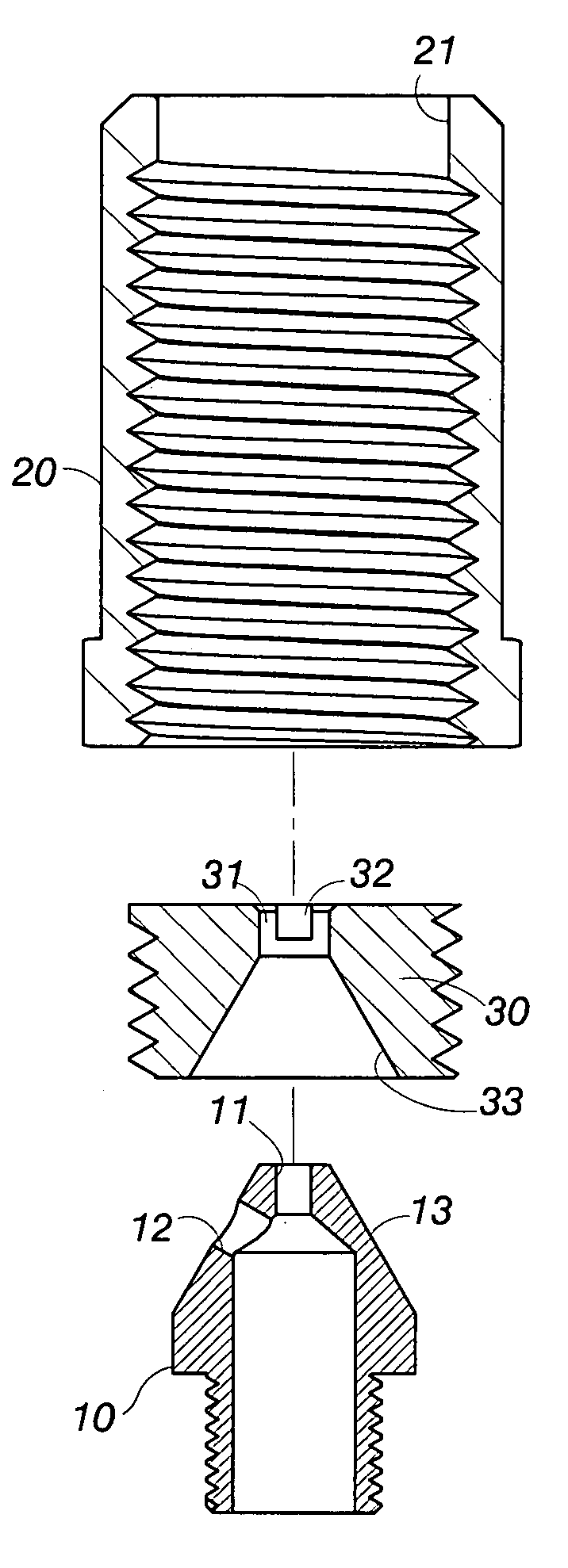
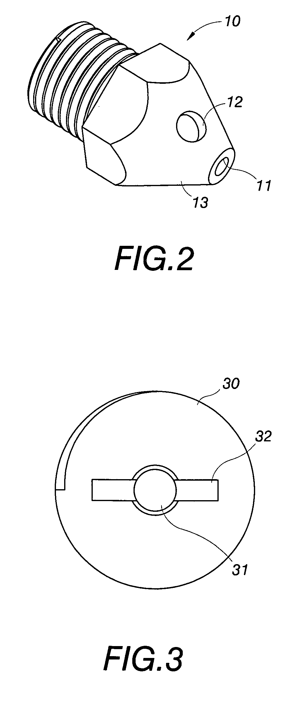
[0037]As illustrated in FIG. 1, a multifunctional fuel gas nozzle according to the present invention comprises a shell 20, a hollow core 10 connected to the fuel gas supply, and a switch strip 30.

[0038]Wherein, as illustrated in FIGS. 1 to 4, said core 10 is a hollow part, the rear end of which is a cylinder with a turned thread on its surface, and the core is fastened to a valve body 40 via the thread and fastened to the rear end portion of the shell 20 through the thread of the valve body 40. The shape of the front end portion 13 of the core 10 is conical, and a liquefied gas hole is disposed on the top surface of the cone to meet the requirements in use of liquefied gas as a fuel; a lateral aperture 12 is disposed on the conical side surface of the front end portion 13, and the sum of the cross-sectional area of the lateral aperture 12 and that of the liquefied gas hole 11 must satisfy the requirements in use of natural gas as a fuel, that is, the sum of the flow volume through t...


PUM


Abstract

The present invention discloses a multifunctional fuel gas nozzle such that the nozzle is generally applicable for both natural gas and liquefied gas with different pressures. The multifunctional fuel gas nozzle of the present invention comprises a hollow core, a shell which is tightly jointed to the rear end portion of the core, and a switch strip which is axially movable with respect to the shell. The above structure is always applicable by switching the switch strip whenever the shell is used for natural gas with a lower input pressure or liquefied gas with a higher input pressure. Therefore, natural gas and liquefied gas with different pressures can share the nozzle only by simple adjustment according to the present invention.

Description

BACKGROUND OF THE INVENTION[0001](a) Field of the Invention[0002]The present invention relates to a nozzle structure for a burner, and, more particularly, to a multifunctional fuel gas nozzle which is capable of adjustment to fit the user and applicable for liquefied gas or natural gas.[0003](b) Description of the Prior Art[0004]Humans have used chemical gas as a fuel for more than one hundred years. The most widely used fuels are natural gas with a lower pressure which is delivered by ducts, and liquefied gas with a higher pressure which is transported by cylinders (commonly referred to as drum gas).[0005]Since the input pressures of both described above are different, the gas valves of liquefied gas furnaces require smaller nozzle diameters thereof due to the higher input gas pressure of the liquefied gas filled in cylinders; the gas valves of natural gas furnaces require larger nozzle diameters thereof owing to the lower gas pressure of the natural gas delivered by ducts. Thus, i...

Claims


Application Information

Patent Timeline
Patent Type & Authority Applications(United States)
IPC IPC(8): F23D11/38
CPCF23D14/48B05B1/30
Inventor TSUNG, KAO-HSUNG
Owner TSUNG KAO HSUNG
Why Eureka
Try Eureka