Implement for engaging planar surfaces while effecting translation movements on those surfaces

a technology of translating movement and planar surface, which is applied in the field of window washing, can solve the problems of difficult preservation high complexity of this type of implement, and inability to meet the needs of the user, and achieve the effects of convenient and rapid adjustment, convenient incorporation into or detachment of the implement, and enhanced reliability

Inactive Publication Date: 2012-12-27
MILLER STEEVEN
View PDF12 Cites 7 Cited by
  • Summary
  • Abstract
  • Description
  • Claims
  • Application Information

AI Technical Summary

Benefits of technology

[0013]Thus, a first objective of the present invention is to develop a versatile implement for engaging planar surfaces while effecting translation movements on those surfaces, which implement is adaptable to be used in combination with a variety of working tools that can be easily incorporated into or detach from the implement.
[0014]A second objective of the present invention is to develop a implement as the above one, wherein the angle between a working tool and its handle can be conveniently and rapidly adjusted to adequately perform the windows' cleaning or alike operations.
[0015]A third objective of the present invention is to develop a implement, as the previous ones, which provides enhanced reliability and extended service life.

Problems solved by technology

Failure to swipe the surface at an optimal angle will lead to streaking and visibly unsatisfactory results.
The main disadvantage of the above disclosed spring-biased pivoting squeegee resides in its relative high complexity for this type of implements.
Hence, it is difficult for this implement to preserve, with the minimum cost of operation, its operation capacity during the stipulated service life.
The above disclosed quick release squeegee constitutes a complicated implement incorporating many parts with special configurations.
This raises the costs of manufacture which has a direct impact on the economic aspect of window cleaning operations.
Moreover, reliability and service life are affected.

Method used


Image

  • Implement for engaging planar surfaces while effecting translation movements on those surfaces
  • Implement for engaging planar surfaces while effecting translation movements on those surfaces
  • Implement for engaging planar surfaces while effecting translation movements on those surfaces

Examples


first embodiment

[0051]Broadly describing with reference to FIGS. 4 through 9, the present invention concerning an implement for engaging planar surfaces while effecting translation movements on those surfaces, generally identified by reference number 20, comprises a head 200 detachably interconnected with a handle 300.

[0052]A projecting insertion element 220 extends centrally and backwards from head 200. Handle 300 comprises a front zone 3001 and a back zone 3002. Front zone 3001 incorporates an internally engaging, frontally open channel 320, exposed to the exterior and shaped to complementarily conform to a shape and size of projecting insertion element 220 and for admitting and snugly capturing the latter with a light-press fit.

[0053]Head 200 extends, centrally and frontally, into a working tool WT. In the case of window cleaning, working tool WT is provided with a wiping blade WP which is detachably and transversally secured to a front end portion of working tool WT.

[0054]One can envisage the u...

second embodiment

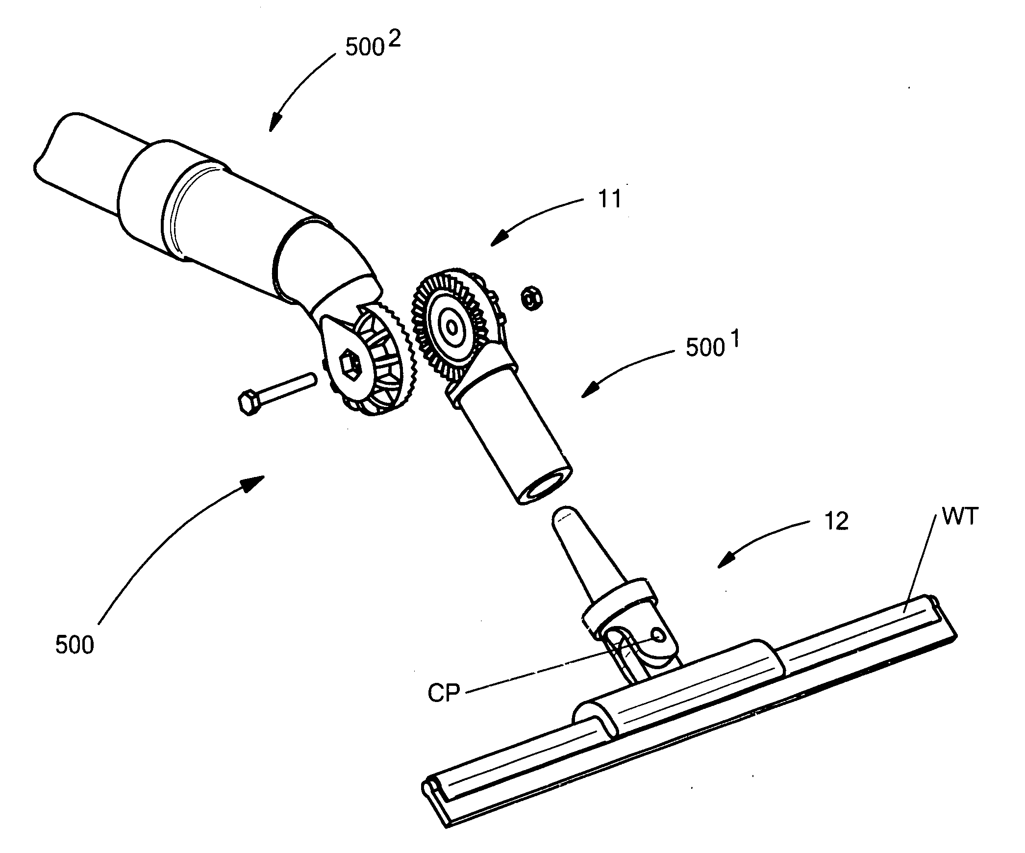
[0059]an implement for engaging planar surfaces while effecting translation movements on those surfaces, described with reference to FIGS. 10 to 12A, generally identified by reference number 40, comprises a head 400 detachably interconnected with a handle 500. Head 400 and handle 500 constitute separate parts.

[0060]A wiping blade WP is detachably and transversally secured to a front end portion of head 400 via working tool WT.

[0061]A projecting insertion element 420, shaped as a splined shaft 430 of conventional type, extends centrally and backwards from head 400.

[0062]Handle 500 comprises a front zone 5001 and a back zone 5002.

[0063]As can be seen from FIGS. 10 and 11, there is an angle between longitudinal axis of front zone 5001 and longitudinal axis of back zone 5002.

[0064]Front zone 5001 incorporates an internally engaging, frontally open elongated orifice 520, shaped to complementarily conform to splined shaft 430 and for admitting and capturing the latter with a tight contact...

third embodiment

[0067]an implement for engaging planar surfaces while effecting translation movements on those surfaces, described with reference to FIGS. 13 to 15, is generally identified by reference number 60, comprises a head 600 detachably interconnected with a handle 700. Head 600 and handle 700 constitute separate parts.

[0068]A wiping blade WP is detachably and transversally secured to a front end portion of head 600 via a working tool WT.

[0069]A projecting insertion element 620, shaped as a cylindrical shaft 630, extends centrally and backwards from head 600.

[0070]Handle 700 comprises a front zone 7001 and a back zone 7002.

[0071]As can be seen from FIG. 14, there is an angle between longitudinal axis of front zone 7001 and longitudinal axis of back zone 7002.

[0072]Front zone 7001 incorporates an internally engaging, frontally open, elongated canal 720, cylindrically shaped to complementarily conform to cylindrical shaft 630. A gap G is provided between internally engaging, frontally open, e...


PUM


Abstract

The implement has a head interconnected to a handle. The head has a projecting insertion element which extends backwardly. The handle includes a front and back zones; longitudinal axis of the front zone intersects longitudinal axis of the back zone. The front zone incorporates an internally engaging, frontally open channel, which complementarily conform to the shape and size of the projection insertion element, so as to admit and snugly capture the projection insertion element. The head has a front end portion for engaging and detachably securing a working tool, for example, a wiping blade for window cleaning or a paint brush. The projecting insertion element has the shape of a spindle, a shape similar to a truncated cone or is cylindrical. The internally engaging, frontally open channel is adaptable to fit to the projecting insertion element.

Description

I. BACKGROUND OF THE INVENTION[0001]1. Definition of the Invention[0002]The present invention refers, in general, to window washing and like devices and, more particularly, to an implement for engaging planar surfaces while effecting translation movements on those surfaces.[0003]2. Description of the State of Art[0004]Window cleaners are usually contracted and endeavor to perform the cleaning process in a rapid manner. Working tools usually require release, replace and securement and, thus, it is important for those operations that the tools are so devised that they require minimal dexterity and physical challenge.[0005]It has been found that the wiping blades (squeegees) will most effectively wipe a surface clean if they are maintained at an optimal angle relative to the working surface. Failure to swipe the surface at an optimal angle will lead to streaking and visibly unsatisfactory results. In order to comfortably handle the squeegee and maintain the wiping blade at a convenient...

Claims


Application Information

Patent Timeline
Patent Type & Authority Applications(United States)
IPC IPC(8): B25G1/06A47L1/06
CPCA47L1/06B25G3/38B25G3/14B25G3/04
Inventor MILLER, STEEVEN
Owner MILLER STEEVEN
Why Eureka
Try Eureka