Ocular Structure for Observation Apparatus

a technology of observation apparatus and ocular structure, which is applied in the direction of telescopes, mountings, instruments, etc., can solve the problem of short lifespan of eyecups in such a design

Inactive Publication Date: 2018-09-27
SINTAI OPTICAL SHENZHEN CO LTD +1
View PDF6 Cites 1 Cited by
  • Summary
  • Abstract
  • Description
  • Claims
  • Application Information

AI Technical Summary

Problems solved by technology

However, the eyecup in such a design has a sho

Method used


Image

  • Ocular Structure for Observation Apparatus
  • Ocular Structure for Observation Apparatus
  • Ocular Structure for Observation Apparatus

Examples


first embodiment

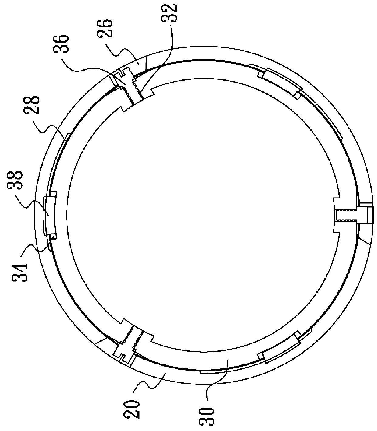
[0035]Referring to FIG. 1, an ocular structure 1 in accordance with the invention includes a main body (not shown), an outer ring 20 and an inner ring 30. The outer ring 20 is configured to move axially relative to the main body and the inner ring 30 and to be selectively positioned in different positions.

[0036]In the first embodiment, the main body is the main part of an observation apparatus (e.g. rangefinder, binocular telescope or monocular telescope) and includes an ocular lens unit. The main body has a first end portion and a second end portion which is closer to the ocular lens unit than the first end portion. The inner ring 30 is connected to the second end portion, and the outer ring 20 is rotatably disposed around the inner ring 30.

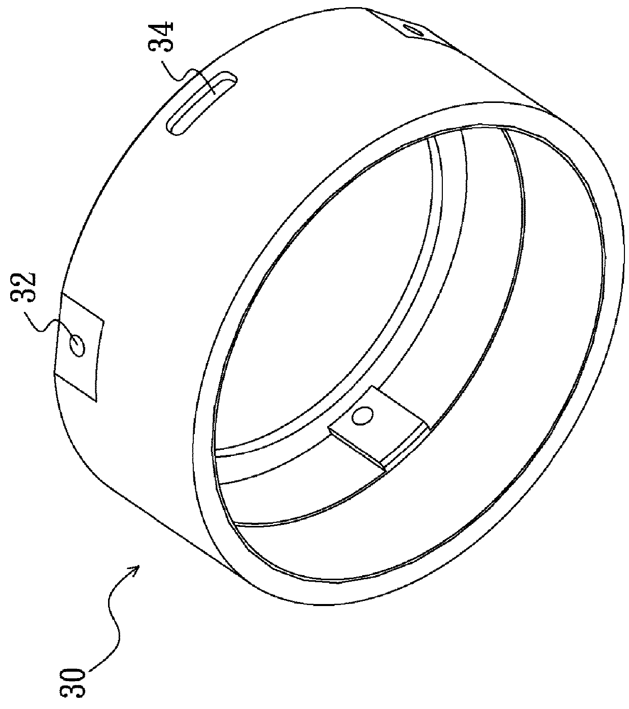
[0037]Referring to FIGS. 1 and 2, the inner ring 30 is provided with at least one through hole 32 and at least one groove 34. As shown in FIG. 1, three sliders 36 corresponding to three through holes 32 are equidistantly disposed on outer circum...

third embodiment

[0043]Referring to FIGS. 1, 4 and 5, the ocular structure 1 in accordance with the above embodiments of the invention includes three positioning elements 38 and three limiting mechanisms 28, and each of the limiting mechanisms 28 includes four limiting grooves 28a-28d at different heights relative to the outer ring 20. However, it is not necessary for the limiting mechanisms to include the same quantity of limiting grooves (or the positioning elements cooperating with the limiting mechanisms may be changed in number). For example (a third embodiment), the ocular structure includes three limiting mechanisms, wherein a first limiting mechanism includes four limiting grooves, a second limiting mechanism includes three limiting grooves, and a third limiting mechanism includes two limiting grooves. Such arrangement generates different levels of tactile feedback to the user during operation. In detail, when the outer ring is in the first position, the ocular structure has three positionin...


PUM


Abstract

An ocular structure for observation apparatus includes a first member, a second member and a main body. The first member includes at least one slot and a plurality of first limiting mechanisms. The second member includes at least one slider extending into the slot and a plurality of second limiting mechanisms. The main body includes an ocular lens unit, wherein the first member and the second member are mounted on the main body. The slider is moved in the slot when the first member and the second member are in relative rotation, and the first limiting mechanisms directly or indirectly match the second limiting mechanisms to position the first member with respect to the second member.

Description

BACKGROUND OF THE INVENTIONField of the Invention[0001]The invention relates to an ocular structure for observation apparatus, and more particularly to an ocular structure including an outer ring capable of moving axially and being positioned in different positions.Description of the Related Art[0002]A conventional observation apparatus (e.g. rangefinder, binocular telescope or monocular telescope) includes an ocular structure which is provided with an eyecup. In operation, the eyecup that is made of rubber can be turned out to adjust a distance between user's eyes and an ocular lens unit. Specifically, the distance is shortened after the eyecup is turned out. However, the eyecup in such a design has a short lifespan due to frequent turning operation. Therefore, the eyecup is required to be made of durable material.BRIEF SUMMARY OF THE INVENTION[0003]The invention provides an ocular structure for observation apparatus capable of moving an outer ring relative to a main body through m...

Claims


Application Information

Patent Timeline
IPC IPC(8): G02B25/00
CPCG02B25/001G02B23/00G02B7/04
Inventor LUO, SHENGCAO, JIA-JUNLIU, HUA-TANGCHEN, YUE-YEGUAN, YU-RONGQIU, KE-YUWANG, CHIAU-JENZHAO, LIAN
Owner SINTAI OPTICAL SHENZHEN CO LTD
Why Eureka
Try Eureka