System and Methods for Dynamic Position Measurement of Ocular Structures

a dynamic position and measurement system technology, applied in the field of ophthalmology and optometry, can solve the problems of weak oct signal, general limited overall accuracy to 5-7 um, and inability to combine accuracy, dynamic range and speed to actively control surgical procedures in real-tim

Pending Publication Date: 2021-07-15
WAVEFRONT DYNAMICS
View PDF0 Cites 1 Cited by
  • Summary
  • Abstract
  • Description
  • Claims
  • Application Information

AI Technical Summary

Benefits of technology

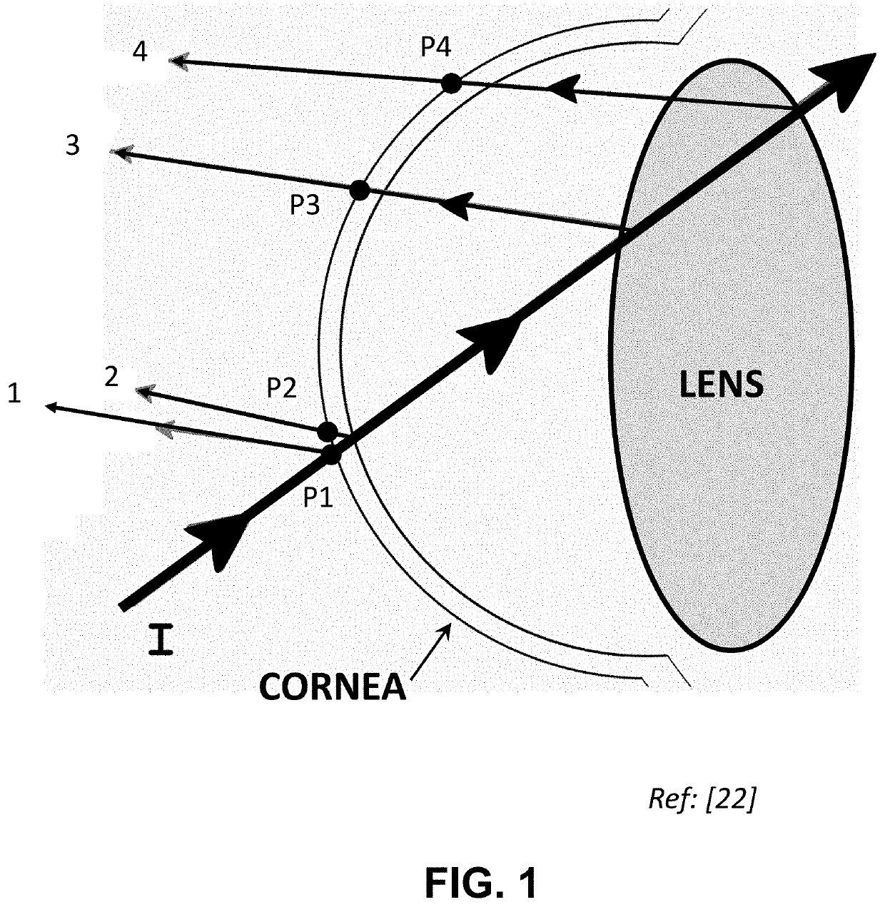
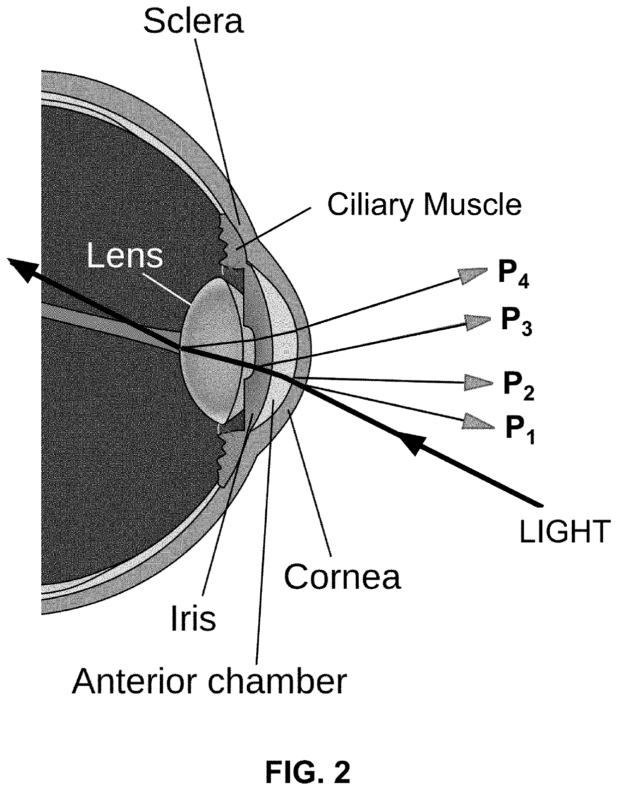
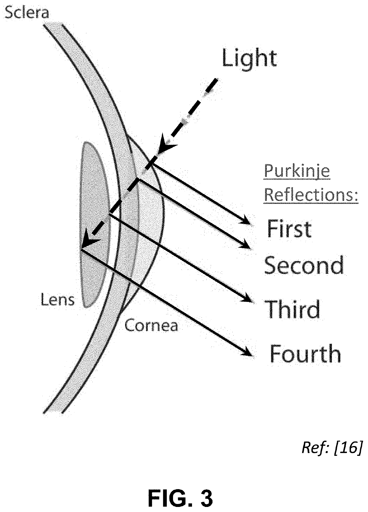
[0051]In principle, it would be sufficient to only use Purkinje-based image analysis to monitor the Z-axis position of an IOL. However, such a data analysis is rather involved, and it might be difficult to do the analysis of the Z-location sufficiently fast for practical use in a real-time system. As an alternative option, the system can combine

Problems solved by technology

However, these techniques are usually aimed at a more general diagnosis of the eye, and generally lack the combination of accuracy, dynamic range, and speed to actively control surgical procedures in real-time.
The overall accuracy is generally limited to 5-7 um, and it involves a complicated system with an X-Y scanner, ray-tracing through the cornea, calibration, and other optical elements.
Another difficulty is that the optical materials used in IOLs are low-scatter, so that the OCT signal is weak.
Data processing is an issue for real-time OCT.
Processing the cross-sectional images to determine the location of each surface is time-consuming.
Accurate tracking of the eyeball's gaze using an eye-tracker device is complicated by these naturally-occurring saccadic motions happening in-between periods of fixation.
It is a very complex optical system, with approximately 35 optical elements.
Disadvantages include: (1) DPI trackers can be very “fiddly” to operate; (2) the head must be restrained with a bite-bar; (3) the device is very expensive; (4) the device is basically made by only one company; and (5) gaze signa

Method used


Image

  • System and Methods for Dynamic Position Measurement of Ocular Structures
  • System and Methods for Dynamic Position Measurement of Ocular Structures
  • System and Methods for Dynamic Position Measurement of Ocular Structures

Examples


first embodiment

[0105]FIG. 24 shows a schematic layout of an optical system 8 of a Purkinjenator™ optical device, according to the present invention. Optical system 8 comprises means and a methodology for dynamically controlling the illumination in real-time during the light acquisition process, and for separating any overlapping Purkinje images, even in the presence of complicating reflections. The Purkinjenator™ optical system comprises a telecentric image relay element 24, similar to the “Dynamic Purkinje-Meter” instrument used by Tabernero and Artal [10, 14, 20]. However, there are additional elements in the present invention that are different than the system taught by Tabernero, et al. Note: the words “optical device”, “optical instrument”, “optical system”, and “optical set-up” are interchangeable and mean the same thing. Also, the phrases “eye-tracking” and “gaze tracking” are interchangeable and mean the same thing. The word “IOL positioning”, as it refers to in-vivo movement of an implant...

second embodiment

[0128]FIG. 32 shows a schematic optical layout of a Purkinjenator™ eye-tracking device, according to the present invention. In this version, the rear LEDs 14 are replaced with a Helmholtz LED Source 140. Light from source 140 is collimated by collimating lens 142, which then passes through a perforated Helmholtz aperture (source) plate 144 and on to beamsplitter 16, where it is re-directed through front lens 18 (L1) toward eye 2.

third embodiment

[0129]FIG. 33 shows a schematic optical layout of a Purkinjenator™ eye-tracking device, according to the present invention. In this embodiment, a linear array of rear Helmholtz LEDs 150 is located one focal length from the front objective lens 18 (thus, all rays are collimated in object space).


PUM


Abstract

This invention, a Purkinjenator™ optical system, is an eye-tracker and methodology for tracking Purkinje reflection images from a human eye in real-time, which allows for the XYZ position and tip/tilt of structures inside the eye to be determined in real-time. When used in combination with programmable groups of IR LED light sources, unique patterns of Purkinje reflections from internal surfaces (and corneal surfaces) can be identified. Thus, XYZ positioning and tip/tilt of internal structures can be accurately and rapidly determined. An Optical Coherence Tomography (OCT) optical system can be combined with the Purkinjenator™ optical system to provide Z-axis distance information.

Description

CROSS-REFERENCES TO RELATED APPLICATIONS[0001]This application claims a priority benefit of U.S. Provisional 62 / 959,127 filed Jan. 9, 2020; and U.S. Provisional 63 / 085,391 filed Sep. 30, 2020, both of which are incorporated herein by reference in their entirety.FIELD OF THE INVENTION[0002]The general field of the invention includes ophthalmology and optometry; and, in particular devices and methods (i.e., eye-trackers) that dynamically tracks the motion and gaze of a human eye in real-time during an ophthalmologic procedure. For example, an eye-tracker can be combined with laser keratotomy (e.g., “LASIK”) to improve the placement accuracy and ultimate vision of patients with intraocular optical lens (IOUs) implanted in the eye after removal of the natural crystalline lens (e.g., due to a cataract). Also, new techniques have been developed that modify the refractive / diffractive material properties of an IOL (intraocular lens) or ICL (implantable contact lens) in vivo by changing the ...

Claims


Application Information

Patent Timeline
IPC IPC(8): A61B5/11A61B3/14A61B3/113A61B5/00
CPCA61B5/1128A61B3/14A61B3/102A61B5/0059A61B3/113A61B3/028A61B3/1025A61B3/152
Inventor NEAL, DANIEL R.COPLAND, R JAMES
Owner WAVEFRONT DYNAMICS
Why Eureka
Try Eureka