

Baffle assembly for a duct
a technology of ducts and baffles, applied in the field of ducts, can solve the problems of inflexible and expensive duct design, difficulty in assembling/welding each baffle into the duct, and high cos
- Summary
- Abstract
- Description
- Claims
- Application Information
AI Technical Summary
Benefits of technology
Problems solved by technology
Method used
Image

Examples
Embodiment Construction
[0018]Reference will now be made in detail to embodiments of the present disclosure, examples of which are illustrated in the accompanying drawings. Wherever possible, the same reference numbers will be used throughout the drawings to refer to the same or like parts.
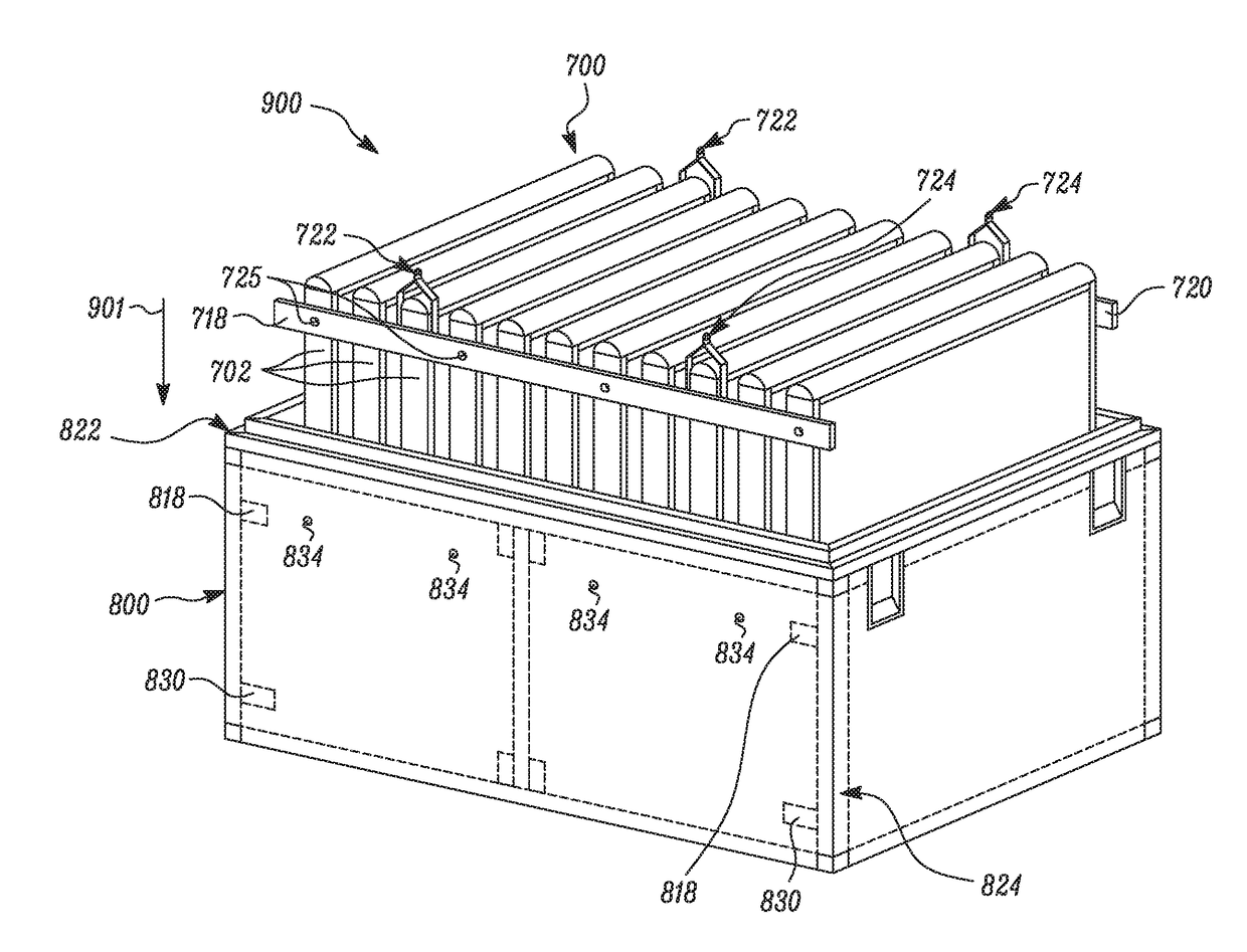
[0019]The present disclosure relates to a noise attenuation baffle assembly configured to be positioned inside a duct. In an example, the baffle assembly may be positioned inside a duct of a turbine engine or a turbine engine enclosure, for suppressing turbine engine noise.
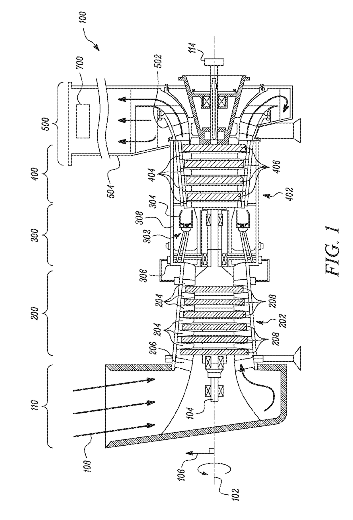
[0020]FIG. 1 is a schematic illustration of an exemplary gas turbine engine 100. Some of the surfaces have been left out or exaggerated (here and in other figures) for clarity and ease of explanation. The disclosure may reference an axis of rotation of the gas turbine engine 100 (“center axis”102), which may be generally defined by a longitudinal axis of its shaft 104. The center axis 102 may be common to or shared with various other engine concentric ...
PUM
 Abstract
Description
Claims
Application Information