Heat treating furnace

Inactive Publication Date: 2018-10-11
REX MATERIALS GRP
View PDF21 Cites 1 Cited by
  • Summary
  • Abstract
  • Description
  • Claims
  • Application Information

AI Technical Summary

Benefits of technology

The patent describes a new type of furnace that uses a layer made of small particles made of fumed silica to improve insulation. These particles are spaced close enough together that air molecules have a hard time moving through them. This results in better insulation without making the furnace bigger.

Problems solved by technology

Indeed, the amount of heat lost by the previously known furnaces is so great that the number of furnaces that may be stacked upon each other is strictly limited due to thermal considerations.
This, in turn, increases the overall manufacturing space and air conditioning requirements necessary during the semiconductor manufacture.

Method used


Image

  • Heat treating furnace
  • Heat treating furnace
  • Heat treating furnace

Examples


Embodiment Construction

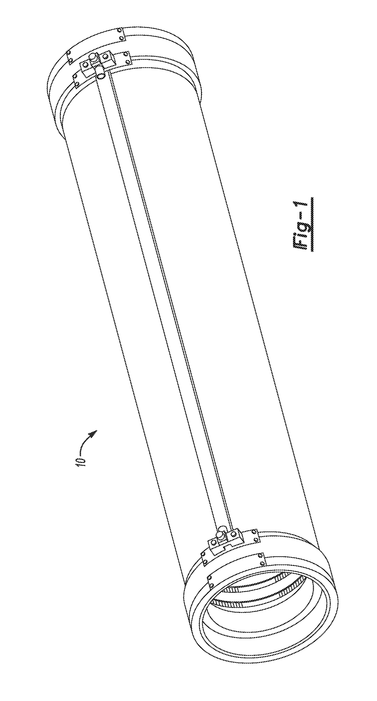
[0016]With reference first to FIGS. 1 and 4, an electrical furnace 10 of the type used for the manufacturing of semiconductor materials is shown. The furnace 10 includes an elongated cylindrical chamber 14 surrounded by an insulation tube 15, typically made of quartz, dimensioned to receive one or more trays or “boats” of semiconductor wafers so that all of the wafers are positioned within the interior of the furnace 10.

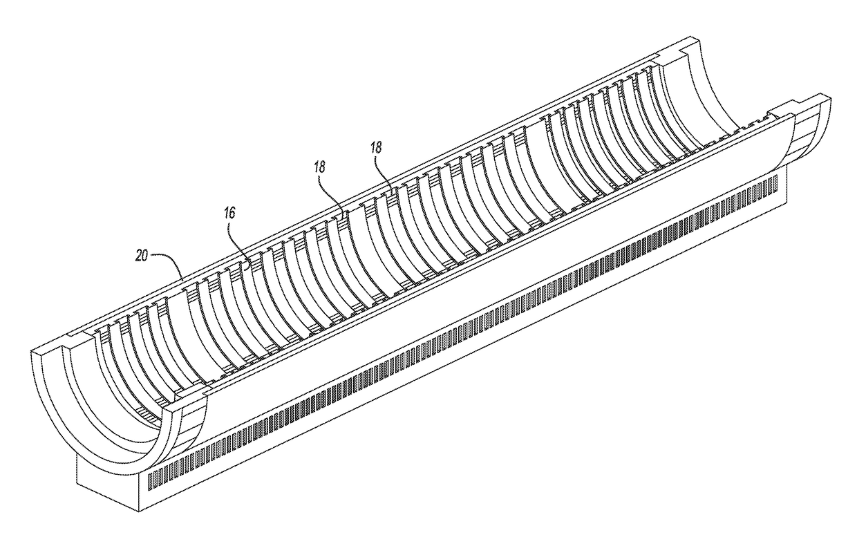
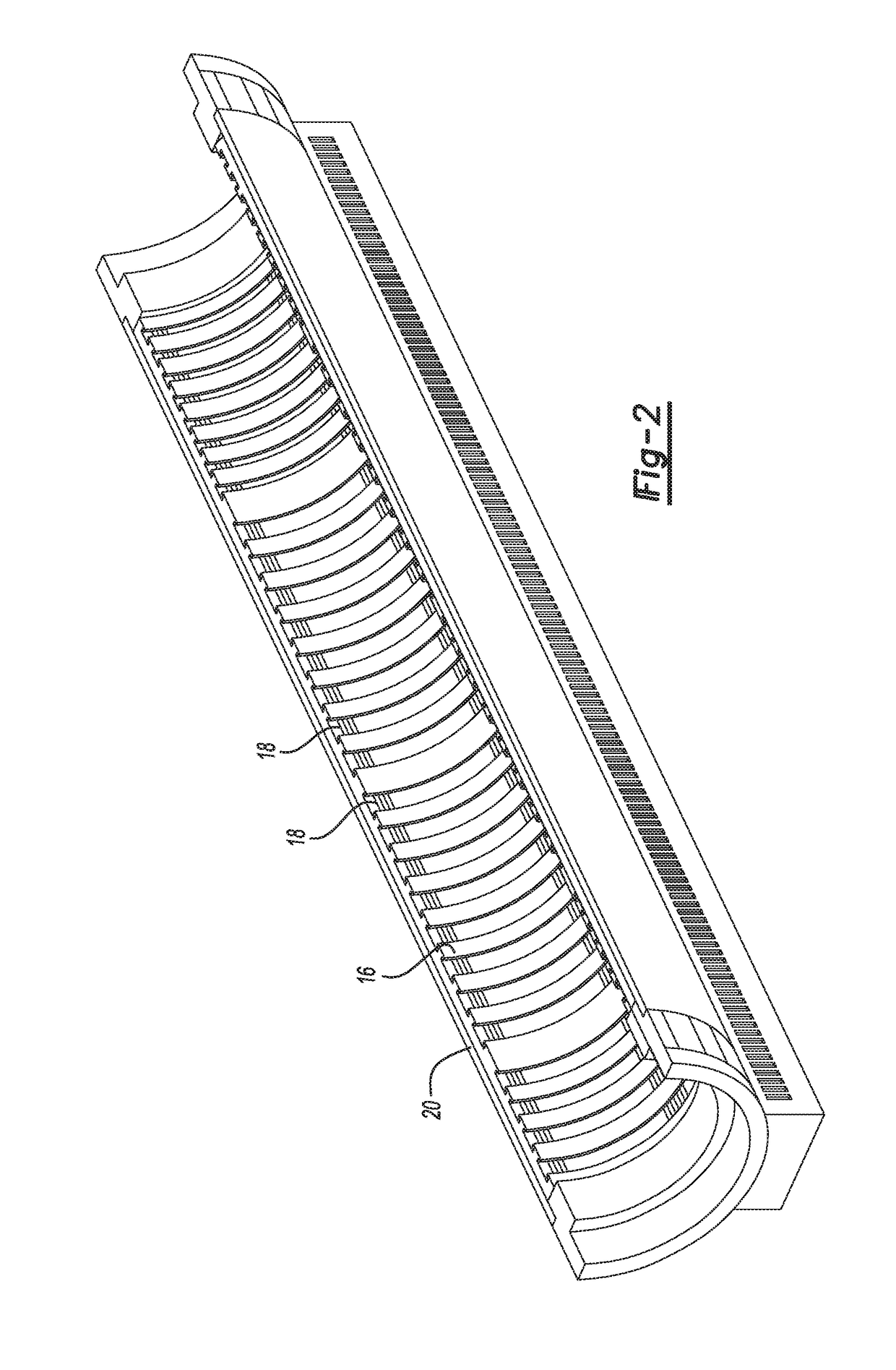
[0017]As best shown in FIGS. 2-4, a ceramic fiber inner layer 16 surrounds the furnace chamber 14. The ceramic fiber 16 is rigid in construction and supports a plurality of electrical heating elements 18 which are open to the chamber 14. Consequently, once the electrical heating elements 18 are connected to a source of electrical power, the heating elements heat the interior chamber 14 of the furnace 10 to the desired temperature necessary to process semiconductor wafers positioned within the furnace chamber 14. Furthermore, the ceramic fiber layer 16 and the electri...


PUM


Abstract

A heat treating furnace of the type used in semiconductor manufacturing having a housing with a tubular and cylindrical inner layer constructed of ceramic fiber. Electrical heating elements are supported by the inner layer while a microporous silica layer surrounds and is in contact with the ceramic fiber layer. A rigid cover surrounds the microporous silica layer.

Description

BACKGROUND OF THE INVENTIONI. Field of the Invention[0001]The present invention relates generally to heat treating furnaces and, more particularly, to a heat treating furnace of the type used in semiconductor and solar cell manufacturing.II. Description of Related Art[0002]There have been many previously known electric heat treating furnaces of the type particularly suited for manufacturing semiconductor electronic components. These furnaces typically are used for oxidation, diffusion of impurities into the semiconductor material and / or CVD of semiconductor wafers.[0003]These previously known furnaces for manufacturing semiconductor wafers typically comprise an elongated tubular housing which defines an elongated tubular and cylindrical heating chamber. The furnace includes an inner ceramic layer which not only defines the chamber to receive the semiconductor wafers, but also physically supports electrical heating elements that are used to heat the chamber to the desired temperature...

Claims


Application Information

Patent Timeline
IPC IPC(8): F27D1/00F27B17/00
CPCF27D1/0033F27D1/0036F27B17/0025
Inventor VONDEMKAMP, TIMSCHENCK, STEVE
Owner REX MATERIALS GRP
Why Eureka
Try Eureka