Golf club head

a golf club and club head technology, applied in golf clubs, golf, sport apparatus, etc., can solve the problems of exacerbating and achieve the effect of reducing the sense of incongruity

Inactive Publication Date: 2018-10-18
SUMITOMO RUBBER IND LTD
View PDF7 Cites 16 Cited by
  • Summary
  • Abstract
  • Description
  • Claims
  • Application Information

AI Technical Summary

Benefits of technology

[0011]With a golf club head according to the present invention, the sense of incongruity can be reduced even when the face is closed at address.

Problems solved by technology

Thus, in the case where the face is closed at address as described above, the orientation of the face is not perpendicular to the target direction, possibly giving rise to a sense of incongruity.
In particular, with a club such as described in JP 2015-29628A, there is a problem in that since a step is formed on the crown portion, the orientation of the face becomes easier to sight, thereby exacerbating the sense of incongruity.

Method used


Image

  • Golf club head
  • Golf club head
  • Golf club head

Examples


working examples

[0058]Hereinafter, working examples of the present invention will be described. The present invention is, however, not limited to the following working examples.

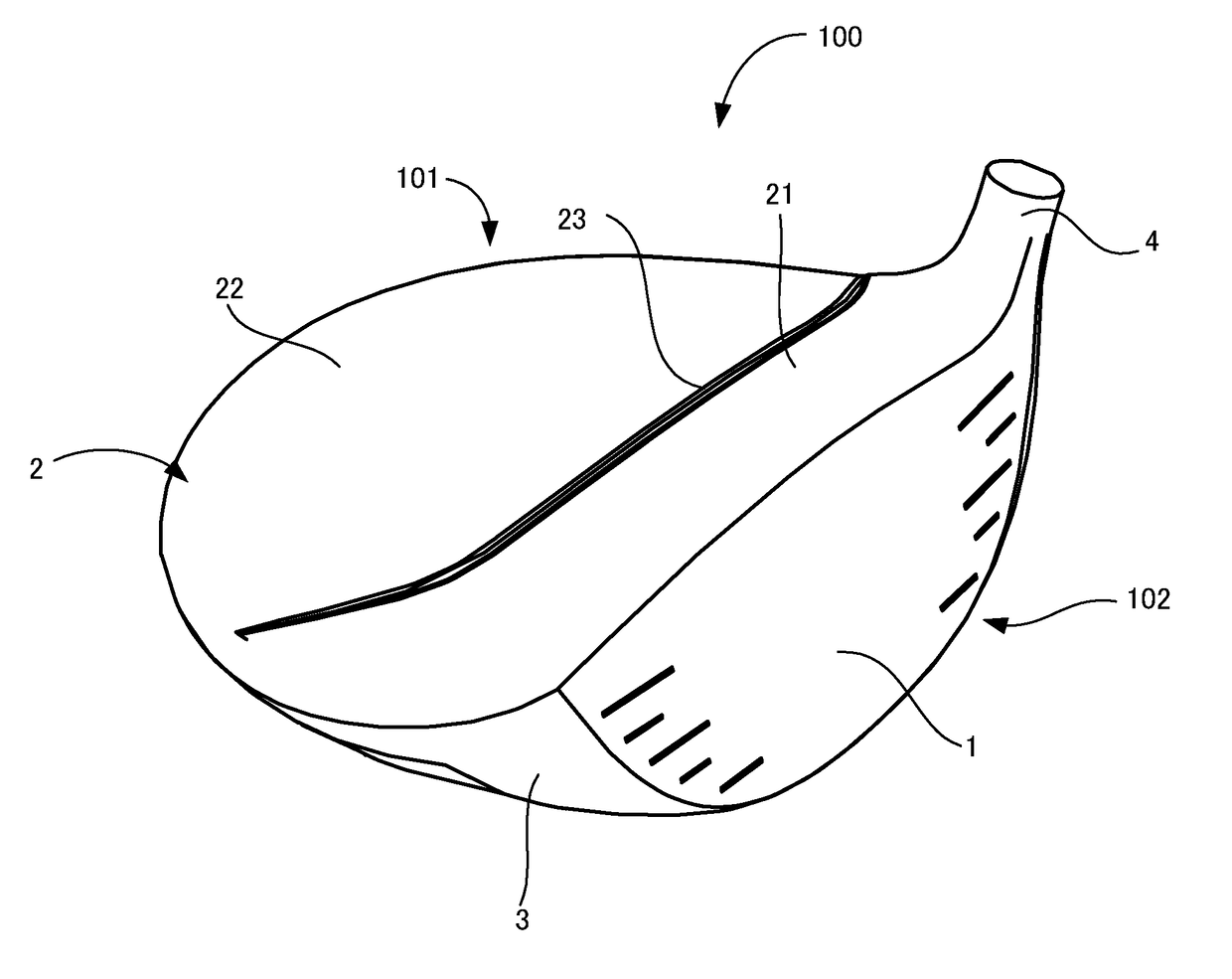
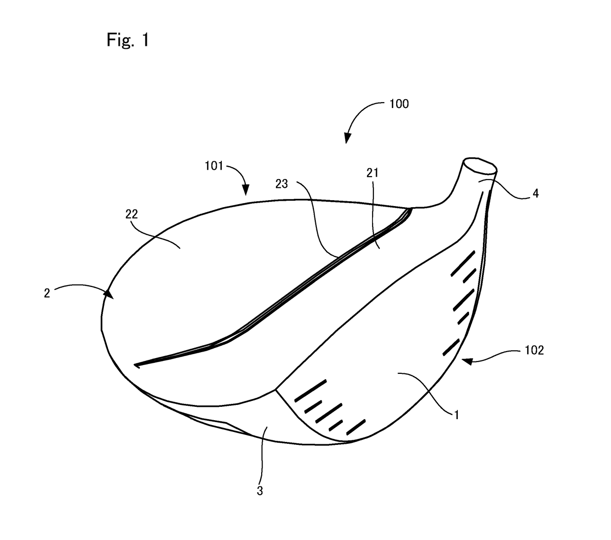
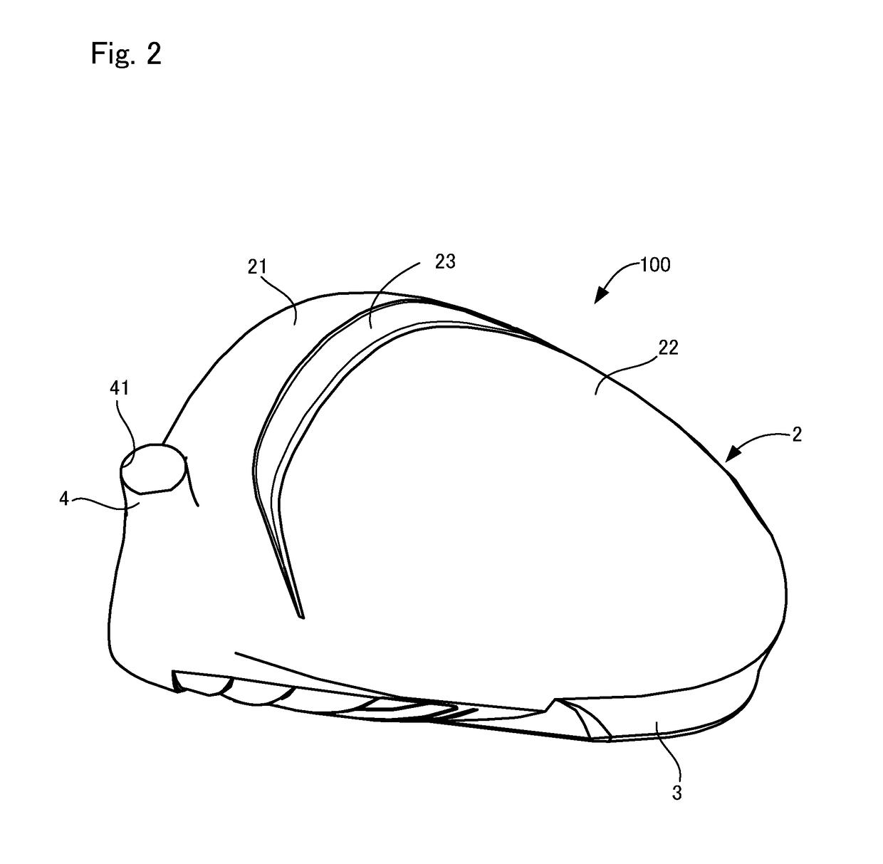
[0059]Here, golf club heads having generally the same shape as FIGS. 1 to 4 were produced as working examples 1 and 2 satisfying the above in equation (1), as described above, and as comparative examples 1 and 2 not satisfying the above in equation (1).

Working example 1Dt / Dh = 1.2 (Dt = 22.0 mm, Dh = 18.3 mm)Working example 2Dt / Dh = 1.3 (Dt = 23.8 mm, Dh = 18.3 mm)Comparative example 1Dt / Dh = 1 (Dt = 18.3 mm, Dh = 18.3 mm)Comparative example 2Dt / Dh = 1.4 (Dt = 25.7 mm, Dh = 18.3 mm)

[0060]Twenty golfers tested the golf clubs produced as described above. That is, sensory analysis was conducted in fine weather conditions as to whether any sense of incongruity was felt when the face surface was closed at address. As a result, with working examples 1 and 2, all of the golfers responded that they did not feel any sense of incongru...


PUM


Abstract

This golf club head includes a face portion, a crown portion and a sole portion, the crown portion including a first region extending along at least part of the face portion, a second region arranged further on a back side than the first region, and a step region extending in the toe-heel direction between the first and the second regions and extending downward toward the second region from the first region side, the first region being formed to at least extend from a position Ph that is 20 mm on a heel side to a position Pt that is 25 mm on a toe side, based on a face center, and a width Dh of the first region in a face-back direction at the position Ph and a width Dt of the first region in the face-back direction at the position Pt satisfying 1<(Dt/Dh)≤1.35.

Description

TECHNICAL FIELD[0001]The present invention relates to a golf club head.BACKGROUND ART[0002]In recent years, golf club heads have been proposed in which a raised portion extending in the toe-heel direction is provided on the crown portion and a sloped surface is formed as a step between the raised portion and the portion rearward thereof (e.g., JP 2015-29628A). A golfer, by sighting this step, is better able to determine the direction of the shot at address.[0003]JP 2015-29628A is an example of related art.SUMMARY OF THE INVENTION[0004]Incidentally, golfers, in order to better catch the ball or to prevent slicing, sometimes intentionally grip the club at address with the face rotated in a direction that closes the face (e.g., in a direction whereby the face is turned to the left of the target direction in the case of a right-handed club). Note that “better catching the ball” refers, for example, to ensuring that the ball is not launched to the right of the intended launch direction (...

Claims


Application Information

Patent Timeline
Patent Type & Authority Applications(United States)
IPC IPC(8): A63B53/04
CPCA63B53/0466A63B2053/0437A63B2053/0441A63B53/0408A63B53/0437A63B53/0441
Inventor MOTOKAWA, YUKI
Owner SUMITOMO RUBBER IND LTD
Why Eureka
Try Eureka