Method and system for clearing a pipe system

a pipe system and pipe system technology, applied in the direction of pipeline systems, hollow article cleaning, chemistry apparatus and processes, etc., can solve the problems of obstructing the filling of the container, obstructing the flow of pipe contents, and not being able to follow the pipe content while the pipe is empty, so as to achieve the effect of reducing the pressure of the sour

Active Publication Date: 2018-10-18
FLUIDOR EQUIP
View PDF7 Cites 4 Cited by
  • Summary
  • Abstract
  • Description
  • Claims
  • Application Information

AI Technical Summary

Benefits of technology

[0017]In an embodiment, the controlling the air supply to the proximal end of the pipe system comprises using a difference between the estimated contents travel speed and a preset contents travel speed value. This effectively allows the contents to be travelling in the pipe system at a predetermined preset speed.
[0018]In an embodiment, the controlling the air flow at the proximal end of the pipe system comprises controlling a regulation valve between the air supply and the proximal end of the pipe system. The controllable valve allows continuous real time control of the air supply into the pipe system, thus the contents travelling speed can be maintained constant at the preset speed.
[0019]In an embodiment, the air supply comprises a compressed air container having a container volume. This is advantageous since the compressed air required for the clearing of the pipes can be loaded into the compressed air container which is then available for fast release in the push phase, alleviating compressed air sources from providing large quantities of compressed air at once.

Problems solved by technology

In the latter case, the pipe system contents were completely expelled prematurely.
When an insufficient normalized amount of contents have been cleared, or when the push phase end prematurely relatively large normalized amounts of contents remain in the pipe system.
When too much contents are cleared from the pipe system in the push phase, compressed air may undesirably enter a container used for capturing contents removed from the pipe system, i.e. product, thereby causing overpressure in such a container and consequently obstructing filling of the container.
As a pipe system may comprise many product feed line or pipes, each of which have to be cleared during production, and wherein pipes are made from opaque materials such as stainless steel, it is not possible to follow the pipe content while it is being cleared from the pipe.
Thus completion of the clearing of the pipe system is uncertain.

Method used


Image

  • Method and system for clearing a pipe system
  • Method and system for clearing a pipe system
  • Method and system for clearing a pipe system

Examples


Embodiment Construction

[0045]The invention will be further elucidated by the following description of exemplary embodiments.

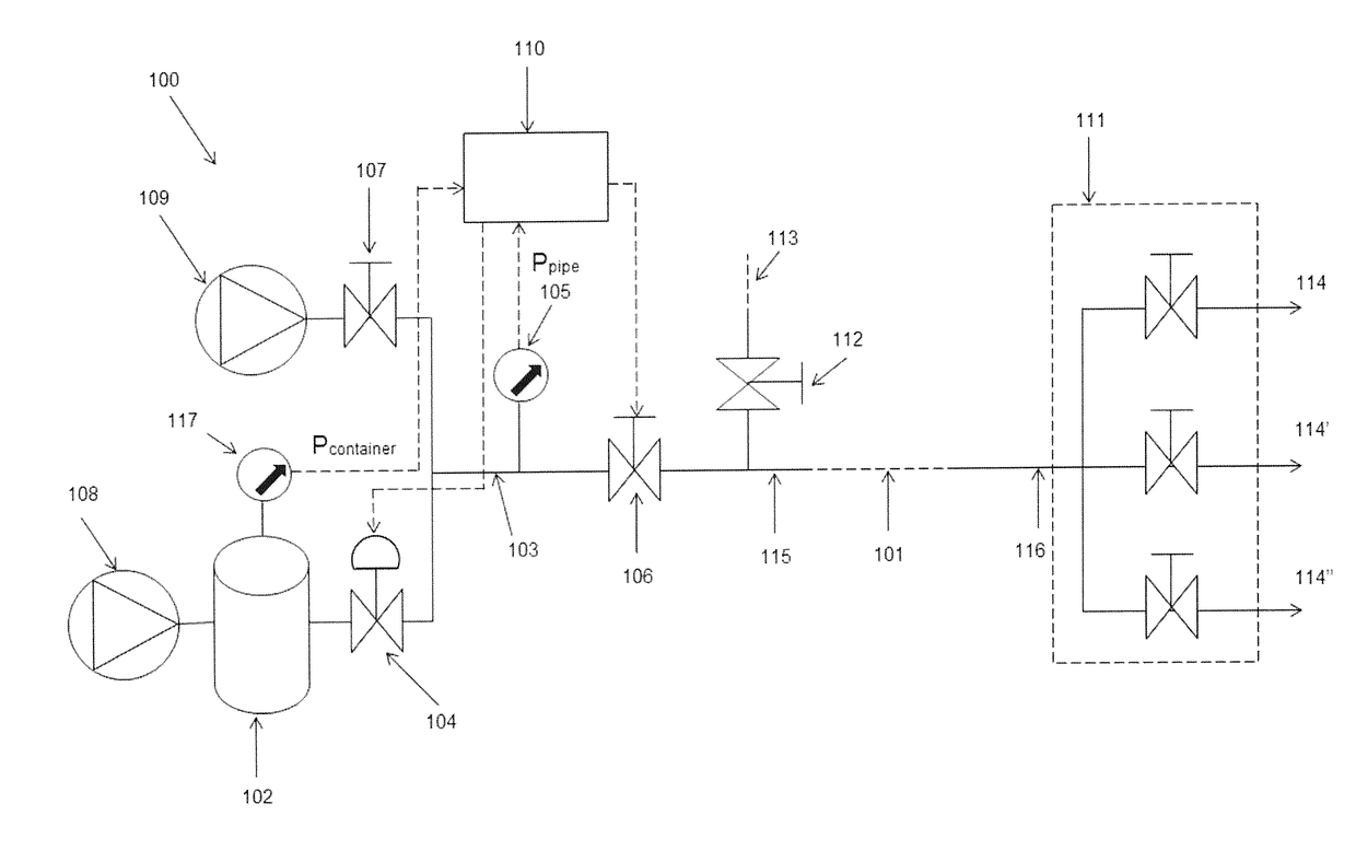
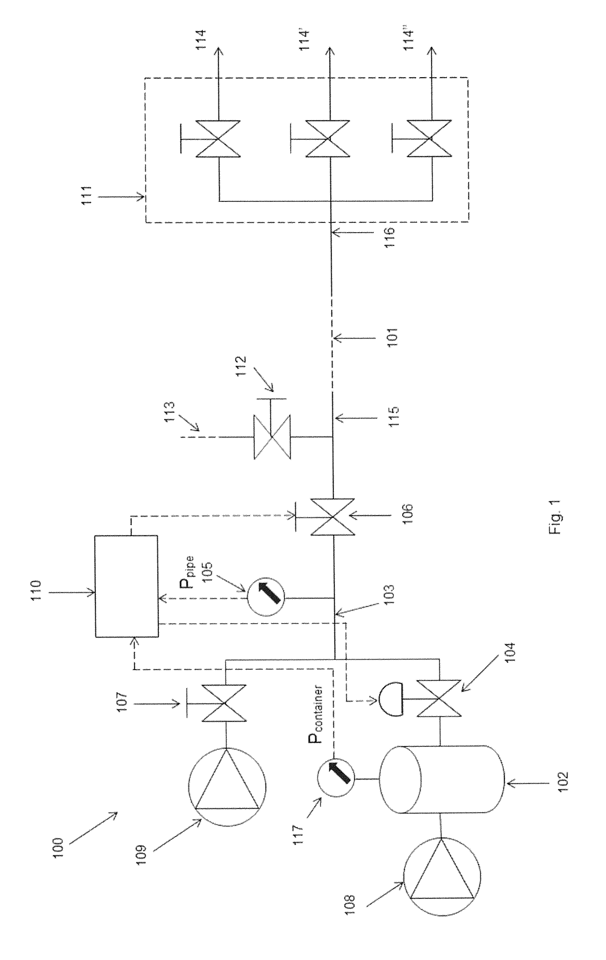
[0046]In FIG. 1 a system 100 is shown for clearing a pipe system 101 from its contents. The pipe system 101 can be supplied with liquid viscous product via line 113, which can be shut off by valve 112. The pipe system 101 has a proximal end 115 near valve 106 and a distal end 116 near an outlet manifold 111. The outlet manifold provides various outlets 114, 114′, 114″ for example for connecting to a further process, a container for content cleared from the pipe system 101, or a separator for separating content from air or rinse fluids used for clearing the pipe system 101. The pipe system 101 can comprise at least one pipe which may be a one-segment pipe. The pipe system 101 may also comprise for example a multi-segmented, bent, curved, bifurcated pipes or a ramification of pipes. The pipes and / or segments may run in different directions, including horizontal, oblique and vertical di...


PUM


Abstract

Method and system for clearing a pipe system from its contents, the pipe having a proximal end and a distal end, the method including providing an air supply to the pipe system at the proximal end by applying an air pressure decreasing from an initial pressure as the bulk of the pipe contents get discharged gradually at the distal end for obtaining a contents flow in the pipe system. The method further includes determining a volume of air supplied to the pipe system by the air supply, determining an estimated contents travel speed from the volume of the air supplied to the pipe and regulating the air supply to the proximal end of the pipe for obtaining a predetermined pipe contents travel speed using the estimated contents travel speed.

Description

FIELD OF THE INVENTION[0001]The invention relates to a method and system for clearing a pipe system.BACKGROUND OF THE INVENTION[0002]Pipe systems are used in industrial environments, for example food industry or oil industry, for transporting contents like raw materials, half products or end products to various stages in corresponding processes. Such pipe systems need periodic cleaning and therefore the pipe system contents, i.e. the product need to be cleared from the pipe system. After clearing the pipe system, cleaning can be performed. Such cleaning is in the art also referred to as ‘Cleaning In Place’ (CIP).[0003]While clearing the pipe system, the cleared contents are preferably preserved for later use or recycling in the process in which the pipe system is used. For this reason is it advantageous to clear the pipe before cleaning by pushing out the pipe system contents using a air. Usually compressed air is used, but dependent on the contents, other gasses may be applicable.[...

Claims


Application Information

Patent Timeline
Patent Type & Authority Applications(United States)
IPC IPC(8): B08B9/032
CPCB08B9/0325B08B9/0328B08B9/0327F17D3/12F17D5/00F17D3/10
Inventor WOUTERS, ROBBERT CHRISTIANUS ANTONIUS
Owner FLUIDOR EQUIP
Why Eureka
Try Eureka