Dispensers

Inactive Publication Date: 2018-10-25
RIEKE PACKAGING SYST LTD
View PDF10 Cites 11 Cited by
  • Summary
  • Abstract
  • Description
  • Claims
  • Application Information

AI Technical Summary

Benefits of technology

[0032]Both these proposals have the advantage of allowing axial overlap (rotational engagement) of the interlock formations between plunger and body collar on depression and turning of the plunger e.g. to a locked-down condition.
[0033]A further proposal to inhibit the disruption of internal seals and also to inhibit relative rotation of components from the outside (especially in combination with other rotational interlocks) relates to the internal structure of the pump body. As mentioned, this body usually must be provided as more than one component in order to mould the desired functional features. For example, an insert portion may be a component separate from a cylinder portion. More preferably a collar po

Problems solved by technology

Shaking, inversion, impact and temperature changes can provoke leakage, either through small clearances and tolerances

Method used


Image

  • Dispensers
  • Dispensers
  • Dispensers

Examples


second embodiment

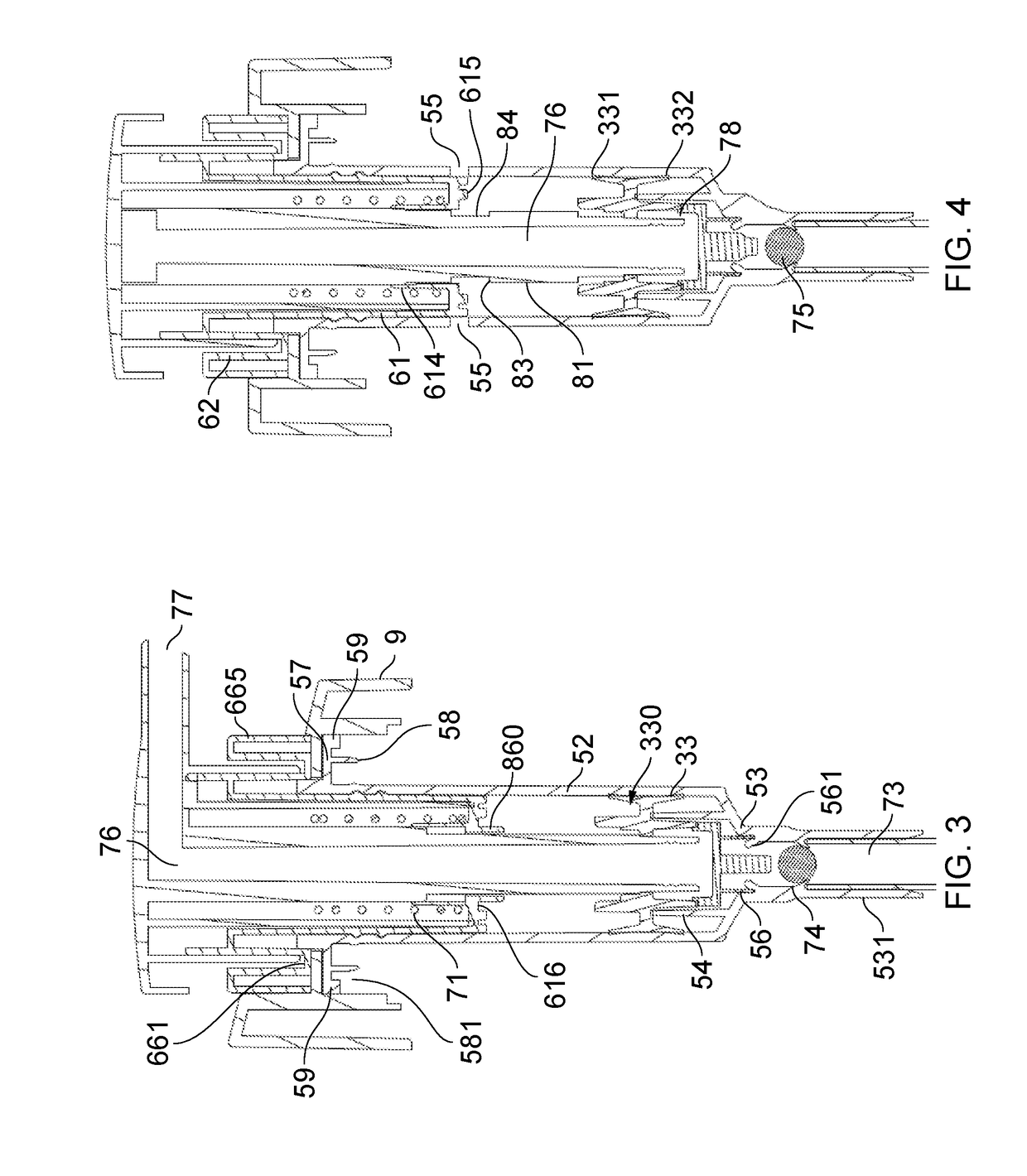
[0110]The bottom of the stem 32 is partly closed off by the end piece 34 (see FIG. 11). The end piece has a set of spaced clip legs 341 engaging the snap ribs inside the stem socket 323, a disc-shaped closure body 346 spaced slightly out from the stem end, and an upward seal ring 342. The underside of the closure body 346 carries a central nose 344 surrounded by a downward sealing skirt 345 which, in the down-position (FIGS. 3, 4), slidingly plugs sealingly into the inlet formation 53 of the cylinder body, around a cylindrical sealing surface 56 thereof, and stopped by inward nib projections 561, blocking communication between the inlet and the pump chamber 79. The piston sleeve 330 has limited travel between upper and lower positions relative to the stem 32. In the upper position (see also FIG. 15 of the second embodiment, where the structures are the same) the inward annulus 336 meets the top slide stop 325 and the bottom seal ring 333 of the sleeve 330 is axially spaced from the ...

third embodiment

[0117]FIGS. 20 to 27 show a third embodiment, in which again the general components correspond to those of the first two embodiments but with the following differences.

[0118]Firstly, the plunger stem is formed with an upper portion—integral with the plunger head as seen in FIG. 24—and a separate lower stem portion which snaps onto the upper stem portion. The lower stem portion carries the opposed pair of uplock / downlock rectangular lands, the top and bottom surfaces of which provide the down-locked and up-locked positions shown in FIGS. 22 and 23, by engagement with the inward projections on the insert component (FIG. 27). As before, the insert component lockdown formations include tracks for passage of the lands on the plunger stem, and stop formations, which are engaged by the ribs seen on the sides of the upper stem portion (FIG. 24). By providing the uplock / downlock formations on a separate stem piece, moulding of the stem and head components is simplified. The lower stem portio...

fourth embodiment

[0129]The fourth embodiment shows a different rotational lock formation for the underside of the closure part of the cylinder body and to engage the container neck (not shown). The formation shown has a set of eight downward projections, outwardly spaced from the inner sealing skirt as before. This is the feature disclosed in our GB1608596.1 filed on 16 May 2016, the disclosure of which is incorporated herein by reference. It is designed to cooperate with a container neck having an upward plug sealing skirt as before, and a pair of two opposed outward projections immediately below the skirt, to engage the body flange lugs shown. In addition to the usual thread, the container neck has directional pawls below the thread to engage flexible directional lugs which project in around the bottom periphery of the outer securing cap (see FIGS. 28 and 29) resulting in a very secure, tamper-resistant closure that will resist considerable agitation and impact e.g. during shipping, without damage...


PUM


Abstract

A dispenser has a plunger (3) operable in a pump body (4). The plunger can be locked up or locked down, and formations (88,89) of a pump plunger stem and pump body insert (6) for achieving this are described. Components of the dispenser, including a pump body cylinder/closure component (5), container neck and a pump body insert (6), are rotationally locked together with non-selective alignment and sealed by sliding-fit seals to prevent damage or leakage caused by relative turning of the components in transit.

Description

FIELD OF THE INVENTION[0001]This invention has to do with dispensers for liquid products, of the type in which a pump consisting essentially of moulded plastics components is mounted on the neck of a container of a liquid to be dispensed, and dispenses the liquid by an action in which a plunger of the pump is moved relative to a body of the pump. Such dispensers are widely used e.g. for dispensing soaps, cosmetics, toiletries, medical creams, lotions and the like.BACKGROUND[0002]Generally, pumps of the kind to which the present proposals relate have a pump body with an inlet to a pump chamber and an outlet passage from the pump chamber to an outlet opening. An inlet check valve assures directional flow, and usually an outlet valve is provided for adequate priming and re-fill of the pump chamber. The pump chamber is varied in volume by movement of the plunger, and usually is defined between a piston and cylinder; typically the piston is carried by the plunger and wipes the inside of ...

Claims


Application Information

Patent Timeline
IPC IPC(8): B05B11/00A47K5/12
CPCB05B11/3059B05B11/3047A47K5/12A47K5/1205B05B11/3023B05B11/306B05B11/3067B05B11/3074B05B11/0044B05B11/1023B05B11/106B05B11/1059B05B11/1067B05B11/1047B05B11/1074
Inventor KNIGHT, SIMON CHRISTOPHER
Owner RIEKE PACKAGING SYST LTD
Why Eureka
Try Eureka