Vehicle lamp

a technology for vehicles and lamps, applied in the field of vehicle lamp assemblies, can solve problems such as distracting the operator of vehicles

Inactive Publication Date: 2018-11-08
FORD GLOBAL TECH LLC
View PDF2 Cites 6 Cited by
  • Summary
  • Abstract
  • Description
  • Claims
  • Application Information

AI Technical Summary

Benefits of technology

[0003]According to one aspect of the present invention, a vehicle lamp is disclosed. The vehicle lamp includes a first light source operably coupled with a lens. A switch is configured to control an activation state of the first light so...

Problems solved by technology

Activation of vehicle interior lamps in low li...

Method used


Image

  • Vehicle lamp
  • Vehicle lamp
  • Vehicle lamp

Examples


Embodiment Construction

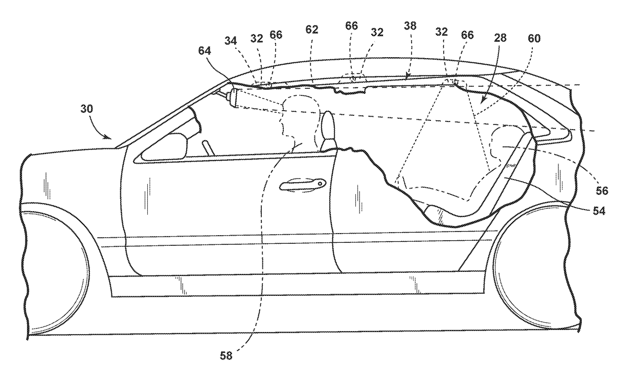
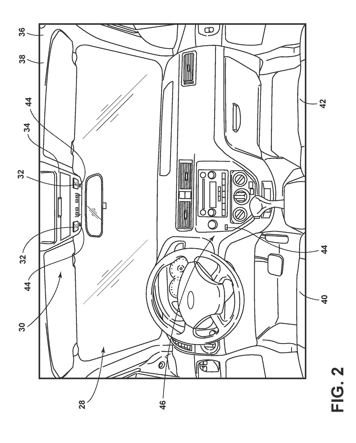
[0019]For purposes of description herein, the terms “upper,”“lower,”“right,”“left,”“rear,”“front,”“vertical,”“horizontal,” and derivatives thereof shall relate to the invention as oriented in FIG. 2. However, it is to be understood that the invention may assume various alternative orientations, except where expressly specified to the contrary. It is also to be understood that the specific devices and processes illustrated in the attached drawings, and described in the following specification are simply exemplary examples of the inventive concepts defined in the appended claims. Hence, specific dimensions and other physical characteristics relating to the examples disclosed herein are not to be considered as limiting, unless the claims expressly state otherwise.

[0020]As required, detailed examples of the present invention are disclosed herein. However, it is to be understood that the disclosed examples are merely exemplary of the invention that may be embodied in various and alternat...


PUM


Abstract

A vehicle lamp is provided herein. The vehicle lamp includes a first light source operably coupled with a lens. A switch is configured to control an activation state of the first light source. A controller prompts the first light source to generate a low-intensity light of a first color when a night-like condition is detected and a vehicle is in motion and a high-intensity light of a second color when the vehicle is stationary.

Description

FIELD OF THE INVENTION[0001]The present disclosure generally relates to vehicle lamp assemblies, and more particularly, to vehicle lamp assemblies that may employ one or more luminescent structures.BACKGROUND OF THE INVENTION[0002]Activation of vehicle interior lamps in low light conditions may distract an operator of a vehicle. For some vehicles, it may be desirable to have a lamp that is less distracting upon activation in such conditions.SUMMARY OF THE INVENTION[0003]According to one aspect of the present invention, a vehicle lamp is disclosed. The vehicle lamp includes a first light source operably coupled with a lens. A switch is configured to control an activation state of the first light source. A controller prompts the first light source to generate a low-intensity light of a first color when a night-like condition is detected and a vehicle is in motion and a high-intensity light of a second color when the vehicle is stationary.[0004]According to another aspect of the presen...

Claims


Application Information

Patent Timeline
IPC IPC(8): B60Q3/72F21V5/04F21V9/16H05B33/08B60Q3/82B60Q3/60H05B44/00
CPCB60Q3/72F21V5/04H05B33/0854H05B33/0872F21V9/30B60Q3/60F21Y2115/10F21Y2113/13B60Q2500/00B60Q3/82F21V9/38F21S10/023F21V23/0442F21Y2113/10F21W2107/10F21W2106/00B60Q3/745B60Q3/80H05B45/20
Inventor SALTER, STUART C.SURMAN, JAMES J.DELLOCK, PAUL KENNETHSINGER, JEFFREY
Owner FORD GLOBAL TECH LLC
Why Eureka
Try Eureka