Direct-view, compact short wave infra red (SWIR) viewer

a short wave infra red and viewer technology, applied in the field of imaging devices, can solve the problems of reducing the us military's advantage during low light operations, user's inability to see any scene detail, and the inability to generate images by the night vision devi

Inactive Publication Date: 2010-04-27
UNITED STATES OF AMERICA
View PDF9 Cites 7 Cited by
  • Summary
  • Abstract
  • Description
  • Claims
  • Application Information

AI Technical Summary

Benefits of technology

[0009]There is a need for a device that uses the 1-2 micron wavelength band. The Direct-View, Compact Short Wave Infra Red (SWIR) Viewer is a multi-purpose device for use in rugged environments. The viewer consists of a lightweight housing, interchangeable objective lens, miniature SWIR imaging sensor, display panel, display electronics, power supply electronic board, controls, and an eyepiece. The compact design allows for the viewer to be handheld, head or helmet mounted, and / or tripod mounted. An integrated display and eyepiece allow the viewer to be a direct-view, i.e., in the direct path with the user's line of sight, device. A video signal generated by the viewer can be exported. The viewer can also display external video signals.

Problems solved by technology

The proliferation of night vision technologies has placed devices into the hands of US adversaries, thereby reducing the US military's advantage during low light operations.
One disadvantage with I2 tube night vision devices is I2 tube night vision devices can not generate an image as a video signal that can be displayed on a monitor or transmitted externally.
Too much light can over saturate the I2 tube and prevent the user from seeing any scene detail.
Therefore, an I2 device can only be used in low-light conditions.
So if an adversary has an I2 device, any opposing force using near IR illuminators or lasers may inadvertently disclose their position.
Additional disadvantages are the narrow applications the night vision devices are designed for.
However, the AN / PVS-14 does not have video output, power input, or external video input capabilities.
Additionally, the AN / PVS-14 does not accept alternative objective lenses other than magnifiers that narrow the field of view.
But the Pocket Scope MK-880 is still susceptible to too much light, the inability to export the amplified image, and the inability to display external video.
However, the PMTV can not display an external video.

Method used


Image

  • Direct-view, compact short wave infra red (SWIR) viewer
  • Direct-view, compact short wave infra red (SWIR) viewer
  • Direct-view, compact short wave infra red (SWIR) viewer

Examples


Embodiment Construction

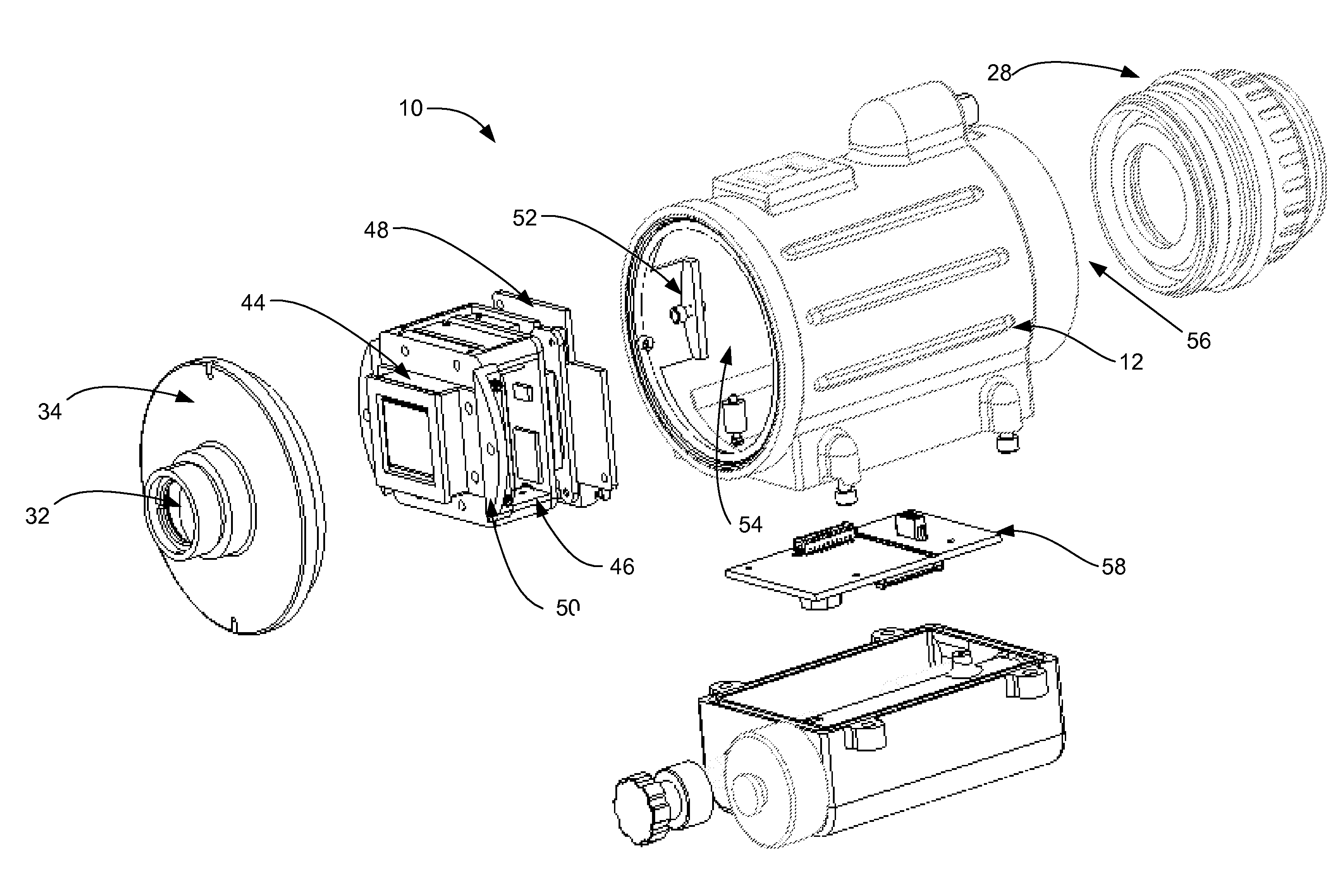
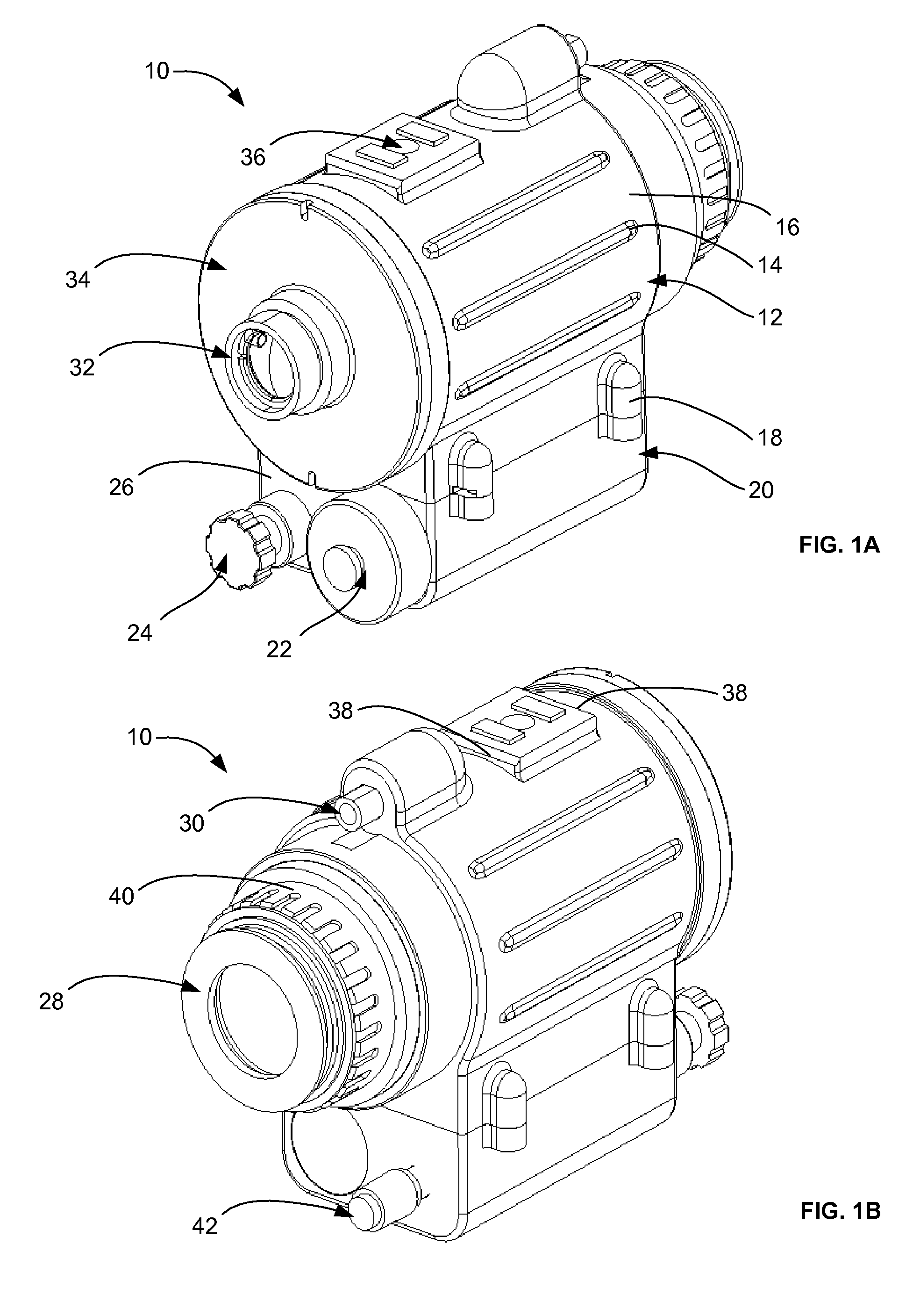
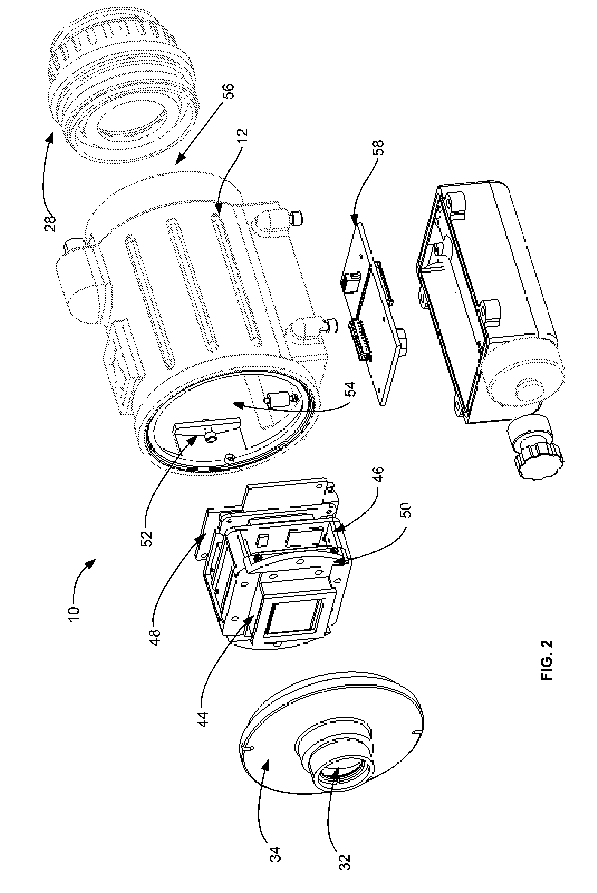
[0033]Referring now to the drawings, and initially to FIGS. 1A and 1B, a Direct-View, Compact Short Wave Infra Red (SWIR) Viewer 10 is illustrated according to one embodiment of the invention. The viewer 10 includes a center housing 12 molded from a rugged, non-metallic housing that allows the viewer to be light-weight and strong. Raised ribs 14 along an outer surface 16 of the viewer increase the gripping surface when holding the viewer. Fasteners 18, for example, screws, latches or the like, removably fasten a battery compartment 20 to the center housing 12. A removable battery cap 22 and Off / On / Display External Video knob 24 are located on a front wall 26 of the battery compartment. The battery cap 22 retains replaceable batteries which are installed coaxially. The Off / On / Display External Video knob 24, located at the front wall 26 of the viewer set's the operational mode.

[0034]The modes are Off, On, and Display External Video signal. In Off mode, the viewer 10 is non-functional....


PUM


Abstract

A night vision device includes an objective lens assembly, an image detector assembly, an eyepiece lens assembly and a housing. The objective lens assembly receives low intensity light. The image detector assembly converts the low intensity light into a visible output image. The eyepiece lens assembly provides for viewing the output image from the image detector assembly. The housing receives the objective lens assembly, the image detector assembly, and the eyepiece lens assembly. Additionally, the housing aligns the objective lens assembly with the image detector assembly and the eyepiece lens assembly along an optical axis.

Description

GOVERNMENT INTEREST[0001]The invention described herein may be manufactured, used, sold, imported, and / or licensed by or for the Government of the United States of America.FIELD OF THE INVENTION[0002]The present invention generally relates to imaging devices that utilize wavelengths of the electromagnetic (EM) spectrum and more particularly to a direct-view, compact short wave infra red (SWIR) viewer.BACKGROUND OF THE INVENTION[0003]The primary head worn, night vision devices used by the United States (US) military are night vision goggles (NVGs). Although these devices can be monocular (one eye looking at an image), biocular (two eyes looking at the same image), or binocular (two eyes looking at two images) in design, conventional NVGs all use image intensification (I2) tube technology. An I2 tube multiplies ambient visible and near IR light several thousands of times. I2 tube technology allows a user to see and operate in very low light conditions. In extreme low light conditions ...

Claims


Application Information

Patent Timeline
Patent Type & Authority Patents(United States)
IPC IPC(8): G02B23/00
CPCG02B23/12
Inventor RAMBOYONG, LENARD V.FUNG, YAU L.
Owner UNITED STATES OF AMERICA
Why Eureka
Try Eureka