Method and apparatus for conserving battery for operation of a low intensity optical communication probe

a low-intensity optical communication and probe technology, applied in the field of optical communication devices, can solve the problems of increasing the complexity of servicing appliances, small electronic integrated circuits that do not lend themselves to troubleshooting and repair methods, and malfunctions in electronically controlled appliances that are more difficult to diagnose and resolve than those of old mechanical cam controlled devices, so as to save the life of batteries

Active Publication Date: 2005-02-03
NIDEC MOTOR CORP
View PDF33 Cites 7 Cited by
  • Summary
  • Abstract
  • Description
  • Claims
  • Application Information

AI Technical Summary

Benefits of technology

[0010] The present invention addresses the above need, as well as others, by providing a battery pack for powering a communication probe that is used for optical communication between an external device and a diagnostic tool. The battery pack comprises a battery for powering a communication probe and a switch for selectively coupling the battery to a cable for delivering electrical power from the battery to the communication probe, the switch being coupled to the power leads of the battery and also being coupled to a power status signal from a diagnostic tool so that the switch selectively couples the battery to the cable so electrical power may be delivered to the communication probe in response to the power status signal from the diagnostic tool indicating the diagnostic tool is an active state. Thus, the switch helps conserve the life of the battery by using a signal that is typically available from handheld computers or personal digital assistants (PDA) that are battery powered. The addition of the switch to the battery pack is a relatively minor modification to the design and construction of the battery pack.
[0012] The battery pack of the present invention may also include a battery charger circuit that is coupled to the battery. The battery charger circuit is adapted to coupled to an AC power source so the battery charger may be used to re-charge the battery when the battery charger circuit is coupled to the AC power source. The battery of the present invention may be coupled to the communication probe by a cable. Alternatively, the battery may be directly coupled to the communication probe through a positive and negative interconnect. The interconnect permits the battery pack and communication probe to be more closely integrated in spatial relationship.

Problems solved by technology

However, the use of electronic controllers has added to the complexity of servicing appliances.
Small electronic integrated circuits do not lend themselves to the methods of troubleshooting and repair that have historically been used with mechanical and electromechanical devices.
Accordingly, malfunctions in an electronically controlled appliance are more difficult to diagnose and resolve than those of the old, mechanical cam controlled devices.
Coupling the communication probe to the diagnostic tool battery power is not favored because the drain of both the diagnostic tool and the communication probe on the diagnostic tool battery may substantially reduce its life.
However, providing a separate battery for the communication probe still presents the issue of how to extend the life of the battery for the communication probe because a user does not want to carry a large supply of batteries so discharged batteries may be replaced during or between service calls.
Furthermore, the interval between service call uses may not be sufficient to recharge one or more batteries from a re-charger that may be located in a service truck or the like.
If a timer is placed on the communication probe battery then it needs to be coordinated with the diagnostic tool so the tool knows when the probe is powered for communication and the complexity of the probe electronics is increased.

Method used


Image

  • Method and apparatus for conserving battery for operation of a low intensity optical communication probe
  • Method and apparatus for conserving battery for operation of a low intensity optical communication probe
  • Method and apparatus for conserving battery for operation of a low intensity optical communication probe

Examples


Embodiment Construction

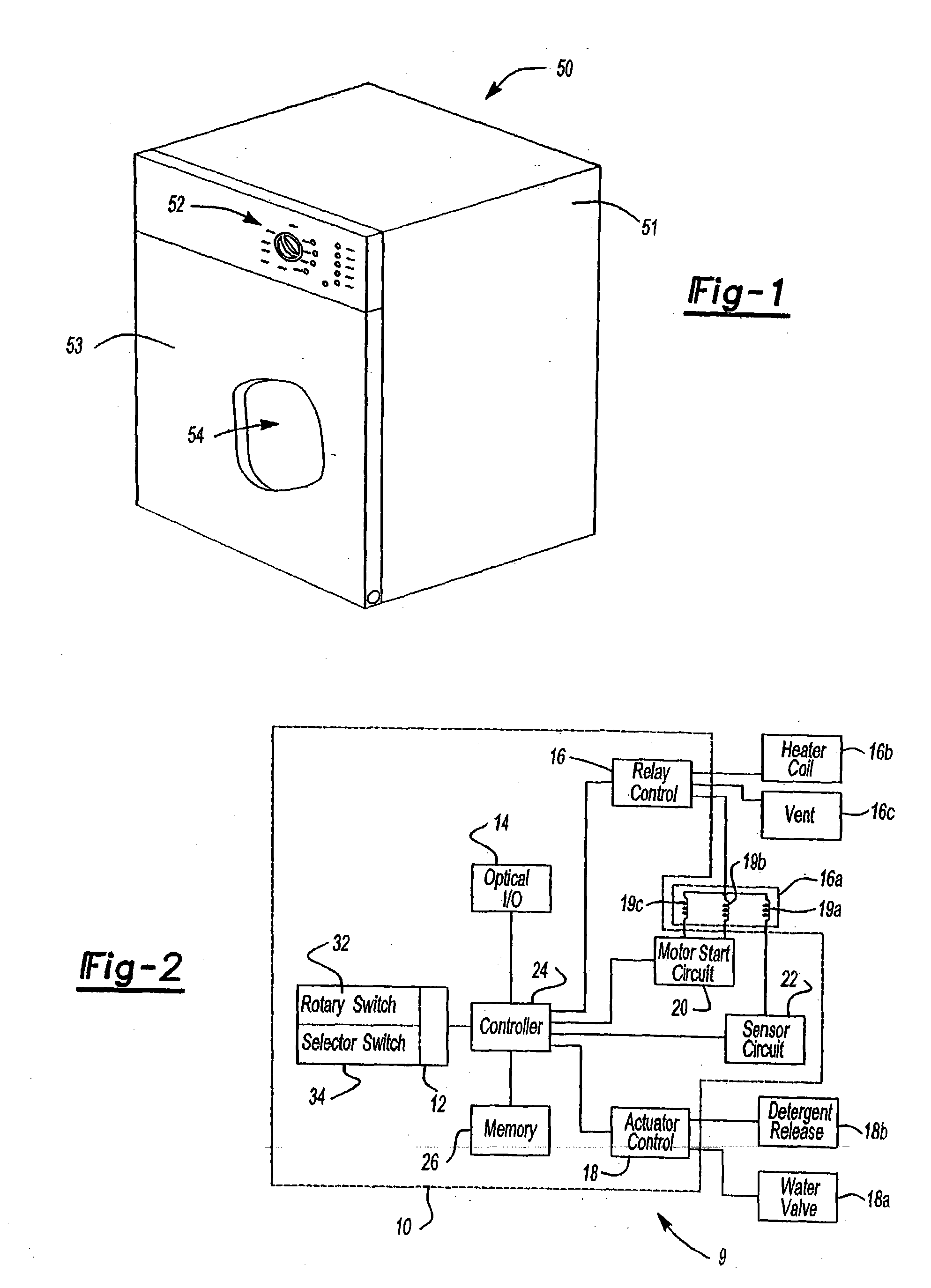
[0036]FIG. 1 shows an exemplary embodiment of a dishwasher 50 in which one or more aspects of the present invention may be incorporated. The dishwasher 50 includes a frame 51, a control panel 52, a door 53, and a tub 54. The door 53 is pivotally attached to the frame 51. The door 53 and frame 51 define an enclosure in which is located the tub 54. The control panel 52 is affixed to the frame 51. The enclosure formed by the door 53 and the frame 51 also houses control circuits and devices as is known in the art. The exact physical arrangements of the door 53, frame 51 and tub 54 are a matter of design choice. For example, the control panel 52 may be mounted on the door 53 in some embodiments.

[0037]FIG. 2 shows a schematic block diagram of an exemplary appliance circuit 9 that incorporates one or more features of the present invention. The appliance circuit 9 includes a control circuit 10 and a set of electromechanical devices. In the exemplary embodiment described herein, the electro...


PUM


Abstract

An optical communication probe enables a diagnostic tool to optically communicate with an external device, such as an appliance, through a low intensity indicator light of the external device. The communication probe is powered by a battery that is selectively coupled to the communication probe through a switch. The switch is coupled to a diagnostic tool to receive a power status signal from the diagnostic tool. In response to the power status signal indicating user inactivity at the diagnostic tool, the switch de-couples the battery from the communication probe to conserve battery life.

Description

[0001] This application cross-references U.S. Provisional Patent Application Ser. No. 60 / 351,348, filed Jan. 24, 2002, and U.S. patent application Ser. No. 10 / 264,888, entitled “Appliance Control Communication Methods and Apparatus” and filed on Oct. 4, 2002, U.S. patent application Ser. No. 10 / 348,305 entitled “System and Method for Communication with an Appliance Through a Light Emitting Diode” and filed on Jan. 21, 2003, and U.S. patent application Ser. No. 10 / 348,305 entitled “System and Method for Communicating with an Appliance Through an Optical Interface Using a Control Panel Indicator,” and filed on Jun. 24, 2003, all of which are hereby expressly incorporated in their entireties by reference.FIELD OF THE INVENTION [0002] The present invention relates generally to optical communication devices, and more particularly, to optical communication devices that use low intensity light signals for communication. BACKGROUND OF THE INVENTION [0003] Appliance devices such as dishwashe...

Claims


Application Information

Patent Timeline
Patent Type & Authority Applications(United States)
IPC IPC(8): H02J9/00
CPCH02J9/005
Inventor ASTRAUSKAS, JURGISPETERSON, GREGORY A.
Owner NIDEC MOTOR CORP
Why Eureka
Try Eureka