
Therapeutic penis ring

a penis ring and ring technology, applied in the field of therapeutic ring vibrators, can solve the problems of not disclosing such ring vibrators, affecting the operation of the chiropractic device, and difficult to achieve manipulation, so as to save battery power and life, facilitate operation, and facilitate the effect of operation

Inactive Publication Date: 2009-12-24
ADAMS JESSE AARON +2
View PDF18 Cites 73 Cited by
  • Summary
  • Abstract
  • Description
  • Claims
  • Application Information

AI Technical Summary

Benefits of technology

[0005]The present invention solves the above-mentioned problems by providing a vibrating barrel with a push button on / off switch that can activate the vibrator quickly and effectively. The push button switch is easy to manipulate under varying environmental conditions, and can be turned on or off in the same way—enabling the user to effortlessly activate and deactivate the device. Furthermore, the push button switch also allows for less wear to the barrel components because there is minimal friction and the contact (to complete the electrical circuit) is made by direct (z-direction) pressure, not lateral force (x- and y-direction pressure).
[0007]The barrel's components are typically aligned along the barrel's longitudinal axis and include a motor and at least one button-cell battery (more in series), in addition to the switch. There will necessarily be connectors to link the battery and the motor. The motor design allows that the invention is extremely durable and conserves battery power and life by its ease of operability that may allow the user to utilize the device a plurality of times before disposal.

Problems solved by technology

The sliding switch is small and requires friction and a force being applied laterally across the end of the barrel—a manipulation that is difficult to achieve during sexual arousal.
Such a sliding switch also effects excessive wear on the internal barrel components (one metal element being chafed against another).
However, these devices comprise various additional projections, bumps, and rings and do not disclose such barrel vibrators as in the present invention.
Nor do they disclose switching mechanisms.
However, Chen's mechanism includes a stick-like design connected to a conductive leaf spring, which could be easily broken or damaged.

Method used


Image

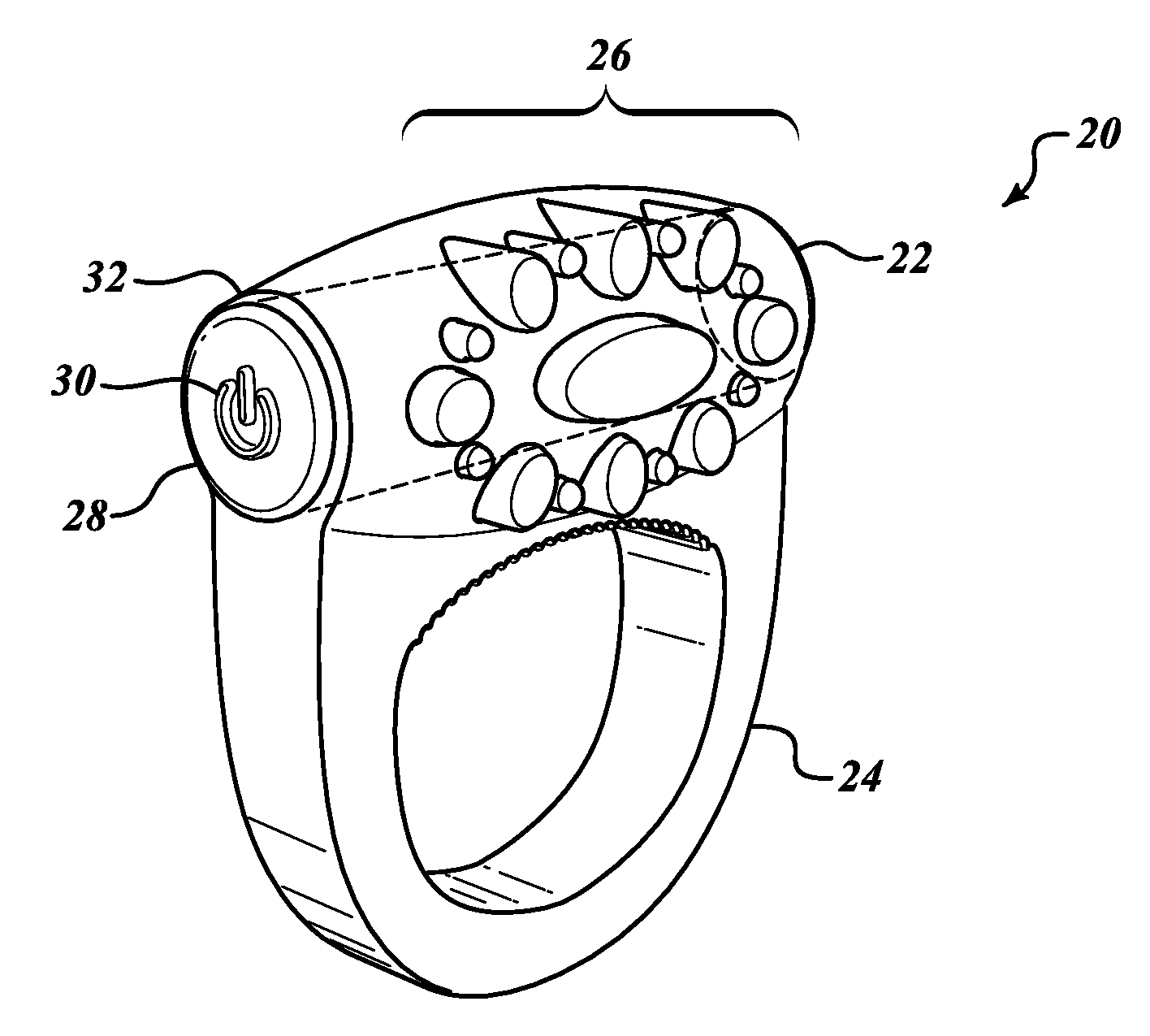
  • Therapeutic penis ring
  • Therapeutic penis ring
  • Therapeutic penis ring

Examples


Embodiment Construction

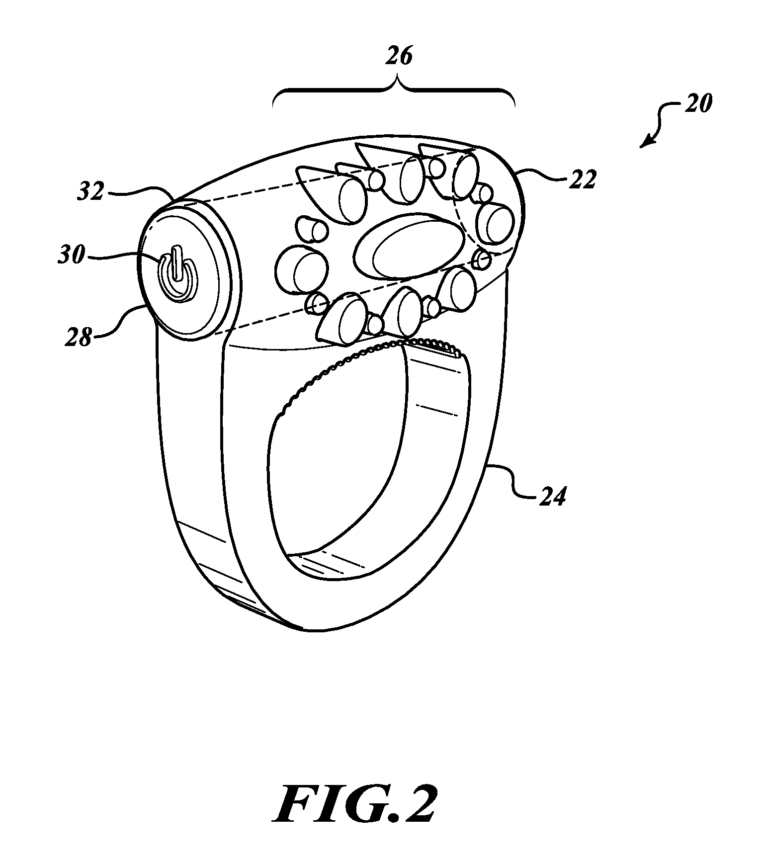
[0014]The following specification describes a therapeutic penis ring with vibrating barrel and method for using. In the description, specific materials and configurations are set forth in order to provide a more complete understanding of the present invention. But it is understood by those skilled in the art that the present invention can be practiced without those specific details. In some instances, well-known elements are not described precisely so as not to obscure the invention.

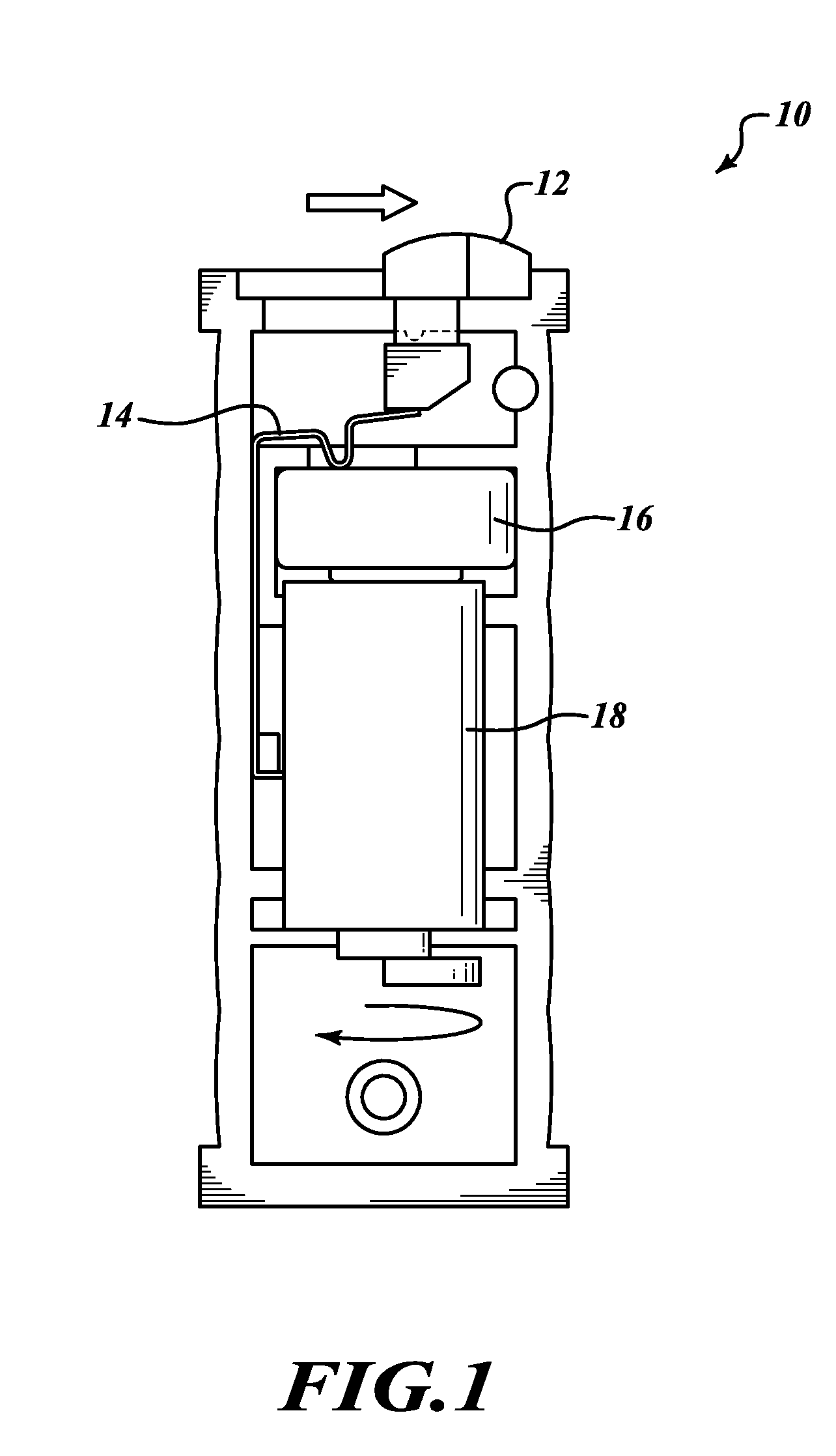
[0015]FIG. 1 shows the prior art vibrator 10 with a sliding switch 12. The figure depicts the vibrator 10 in the “on” position with the connector 14 having been activated to complete the circuit between the battery 16 and the motor 18. A user must apply lateral force in the direction of the arrow and at the same time develop friction with the switch 12. Further, sliding the switch on and off repeatedly causes the connector 14 to bend repeatedly and eventually wear so much that it becomes inutile.

[0016]FI...


PUM


Abstract

The Therapeutic Vibrator is a small barrel-shaped container housing a motor and at least one battery for the electric power source. The Therapeutic Vibrator is typically activated by an on / off switch or push-button at one end of the barrel, and when activated, the barrel will vibrate delivering massage to a specific body part. The barrel may comprise two halves that fasten together having recesses and cavities for battery (typically button-cell type), motor, switch wiring, etc. The barrel may then be contained within an appropriate vibrator body made from a material that is soft to the touch. The Therapeutic Vibrator may be used in a sex toy or in any other appropriate massaging device, such as small massagers for hands or faces.

Description

FIELD OF THE INVENTION[0001]This invention pertains generally to therapeutic vibrators, and more specifically to a therapeutic vibrator in the shape of a small barrel being driven by electric means.BACKGROUND OF THE FIELD[0002]Vibrators in various forms are often used to stimulate parts of the human body. Specifically, vibrators have been used in sex aids to enhance the sexual experience and satisfaction and / or to minimize sexual dysfunction. In sex applications, it is generally desirable that the vibrator be housed in a housing that is soft and also adapted to be held in an appropriate position. There are some prior art patents that have dealt with these issues—e.g., erectile dysfunction, impotence, and lack of satisfaction.[0003]For instance, U.S. Pat. No. 7,108,668 B2 to Fang discloses a battery-operated vibrator that is housed in a penis ring in a soft housing. However, Fang's device is activated by a sliding switch used to complete a motor circuit. The sliding switch is small a...

Claims


Application Information

Patent Timeline
Patent Type & Authority Applications(United States)
IPC IPC(8): A61F5/00A61H1/00
CPCA61F5/41A61F2005/417A61H19/32A61H23/0263A61H2201/165A61H19/34
Inventor ADAMS, JESSE AARONTAI, KENNY CHIH-YANCHIU, KEVIN TZU-HSAUNG
Owner ADAMS JESSE AARON
Learn More