
User interface camera effects

a technology of user interface and camera effect, which is applied in the field of computer user interfaces of electronic devices, can solve the problems of insufficient time for existing techniques, inconvenient use, and inability to manage camera effects using electronic devices, so as to improve efficiency, improve user satisfaction, and improve the effect of efficiency

Active Publication Date: 2018-12-06
APPLE INC
View PDF7 Cites 73 Cited by
  • Summary
  • Abstract
  • Description
  • Claims
  • Application Information

AI Technical Summary

Benefits of technology

The present technology improves the way electronic devices manage camera effects. It provides faster, more efficient methods and interfaces that reduces the burden on users and produces a more efficient human-machine interface. It also conserves power and increases the time between battery charges. The techniques can simulate visual effects in camera viewfinders and captured images without requiring additional hardware components. It enables quick transition between user interfaces with limited user input. It efficiently provides enhanced image editing capabilities and user interfaces for transitioning between different sets of options with minimal input. Overall, it reduces the number of required user inputs and conserve battery power. These improvements increase the effectiveness, efficiency, and user satisfaction with such devices.

Problems solved by technology

Some techniques for managing camera effects using electronic devices, however, are generally cumbersome and inefficient.
For example, modifying the visual effects in viewfinders such that captured images and recorded videos exhibit the visual effects often requires extensive user input and is imprecise.
Existing techniques require more time than necessary, wasting user time and device energy.

Method used


Image

  • User interface camera effects
  • User interface camera effects
  • User interface camera effects

Examples


Embodiment Construction

[0061]The following description sets forth exemplary methods, parameters, and the like. It should be recognized, however, that such description is not intended as a limitation on the scope of the present disclosure but is instead provided as a description of exemplary embodiments.

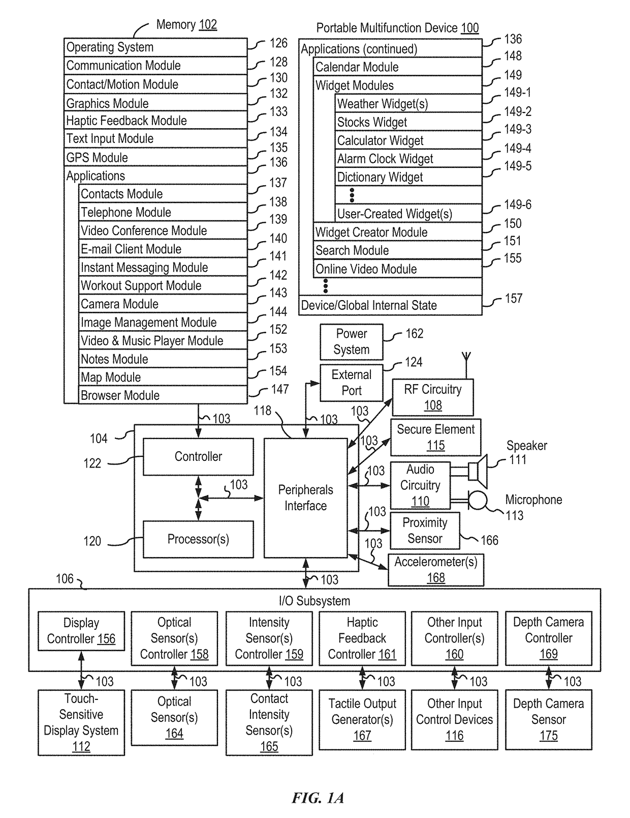
[0062]Electronic device are being designed and manufactured with more advanced camera features and sensors. However, some electronic devices, by nature of their design, are unable to capture the richness of point-of-light photography without additional hardware. Many of the point-of-light photography techniques require numerous and expensive light sources to be positioned around a subject as well as a separate backdrop. However, many electronic devices have only a single flash emitting light in one direction. As a result, many of the point-of-light photography techniques simply cannot be accomplished via traditional electronic devices.

[0063]The embodiments described herein include electronic devices that ut...


PUM


Abstract

The present disclosure generally relates to user interfaces. In some examples, the electronic device provides for transitioning between simulated lighting effects. In some examples, the electronic device applies a simulated lighting effect to an image. In some examples, the electronic device provides user interfaces for applying a filter to an image. In some examples, the electronic device provides for a reduced filter interface. In some examples, the electronic device provides a visual aid displayed in a viewfinder.

Description

[0001]This application claims priority to U.S. provisional patent application No. 62 / 556,414, entitled “USER INTERFACE CAMERA EFFECTS,” filed on Sep. 9, 2017, and U.S. provisional patent application No. 62 / 514,947, entitled “USER INTERFACE CAMERA EFFECTS,” filed on Jun. 4, 2017. The content of both applications is hereby incorporated by reference in its entirety for all purposes.FIELD[0002]The present disclosure relates generally to computer user interfaces of electronic devices, particularly devices with built in cameras.BACKGROUND[0003]The use of electronic devices for recording videos and taking pictures has increased significantly in recent years. Exemplary electronic devices for recording videos and taking pictures include smart phones and hand-held cameras. Such devices frequently include a viewfinder, which the user can use for previewing before taking a picture or recording a video.BRIEF SUMMARY[0004]Some techniques for managing camera effects using electronic devices, howev...

Claims


Application Information

Patent Timeline
IPC IPC(8): G06F3/0484G06F3/0488H04N5/232
CPCG06F3/04847G06F3/04883H04N5/23212H04N5/23216H04N5/23219H04N5/23241H04N5/23245H04N5/23293H04N5/23296G06F3/04817G06F3/0482H04N1/6027H04N23/67H04N23/62H04N23/64H04N23/651H04N23/667H04N23/632H04N23/90H04N23/69H04N23/65H04N23/74H04N23/611H04N23/631G06F3/048G06T7/50G06T15/00H04N1/00H04N23/80G06T5/20G06T5/94H04N23/63
Inventor MANZARI, BEHKISH J.BAREZA, MAREKBRASKET, JEFFREY A.CAO, FREDERICDYE, ALAN C.HARRIS, ELLIOTTIRANI, CYRUS DANIELIVE, JONATHAN P.JOHNSON, GARRETTKIM, EMILIEMALIA, JOSEPH A.PAUL, GRANTPIVONKA, PAVELSORRENTINO, BILLYSOUZA DOS SANTOS, ANDRE
Owner APPLE INC
Learn More