Method and apparatus for robot teaching

a robot and robot technology, applied in the field of industrial robots, can solve problems such as the mental inability to activate an external safety switch, and achieve the effect of removing prior art deficiencies and limitations

Inactive Publication Date: 2012-05-24
SZALEK LESZEK A
View PDF5 Cites 82 Cited by
  • Summary
  • Abstract
  • Description
  • Claims
  • Application Information

AI Technical Summary

Benefits of technology

[0010]The main object of the present invention is to provide a simple apparatus for direct teaching of a robot in safety and a method of teaching a robot, known in the art as a teach-in or guiding method, eliminating the prior art deficiencies and limitations.
[0013]The controller's command computes velocity directive proportional to applied force, however, never exceeding the velocity safe limit preset in the teaching mode of operation. The apparatus electronic circuitry outputs signal when force level exceeds certain minimum level, thus protecting from undesired, too sensitive robot moves and making the apparatus immune to significant temperature drift. It requires the operator to apply a certain amount of force to the handle to engage the tactile sensors in order to output signal at the level that generates move commands. If force exceeds certain maximum level, preset as an upper limit, the apparatus outputs signal of a value equal to that maximum level. The upper limit defines the danger zone when the handle becomes pushed too far. In case the handle of the teaching apparatus makes undesirable contact with the work and the robot is generating power in the direction of force, once the force level exceeds the upper limit, the safety signal is generated and input to the robot main controller to execute command bringing the robot to an immediate halt. It works as an emergency or a dead-man switch, inherently built into to the teaching apparatus. This feature does not require the operator to be alerted all the time and to quickly react when the robot moves into undesired zone. This feature becomes handy when the operator panics or is shocked, thus being mentally incapable to activate an external safety switch. In the final result, this built-in safety mechanism does not require the operator to hold the emergency switch and saves human life or health, significantly lowers operator's fatigue and prevents work damage. Besides, it eliminates a need of a compliance mechanism, making it a simple, cost effective device, especially, if inexpensive resistive force sensors are used.
[0018]Robot and wrist motion commands are generated in response to the force applied to the apparatus handle to power assist the operator in moving the robot arm. The robot arm moves are relative to the current position and last as long as the force is applied to the handle. The relative moves make the mathematical model of the teaching procedure very simple
[0019]The main robot controller provides means to switch to the teaching mode. Once in that mode the controller lowers level of the voltage supplied to servo amplifiers, setting a limit on maximum velocity of motors powering robot arms at the safe level. At the same time, a limit is set to motors current to restrict motors maximum torque level allowing only compensation of the gravity force acting upon the robot arms. These limits imposed by the main controller physically prevent the robot from making unexpected moves that would endanger life or health of the operator. Additionally, the teaching apparatus enables the teaching procedure to be performed within the safety limits.

Problems solved by technology

This feature becomes handy when the operator panics or is shocked, thus being mentally incapable to activate an external safety switch.

Method used


Image

  • Method and apparatus for robot teaching
  • Method and apparatus for robot teaching
  • Method and apparatus for robot teaching

Examples


Embodiment Construction

[0033]The present invention will be described in detail based on the embodiments illustrated in the drawings. The embodiments of the present invention described below are not intended to be exhaustive or to limit the invention to the particular embodiments disclosed in the following detailed description. Rather, the embodiments are described so that others, particularly those skilled in the art may appreciate and understand the principles and practices of the invention.

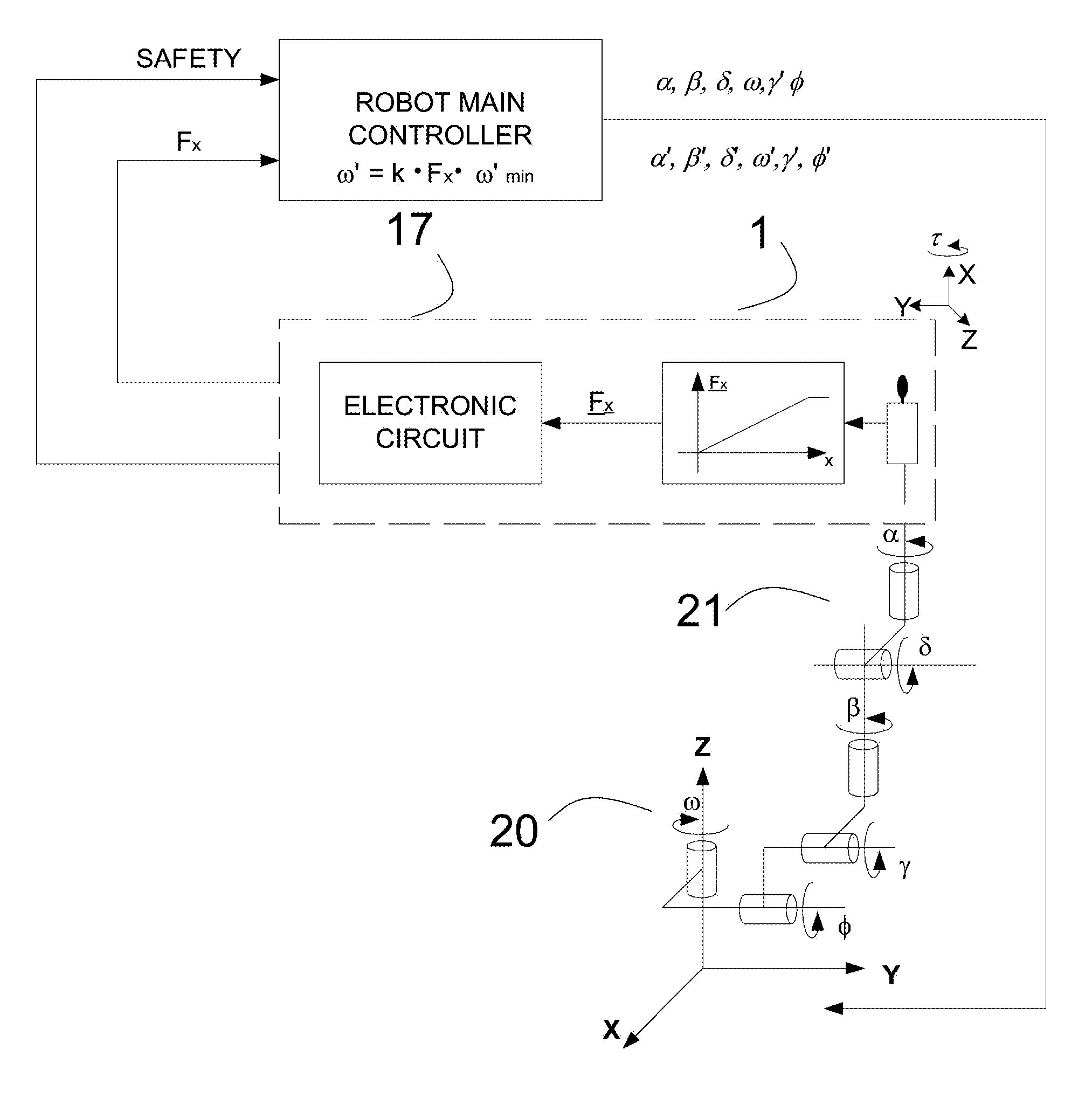
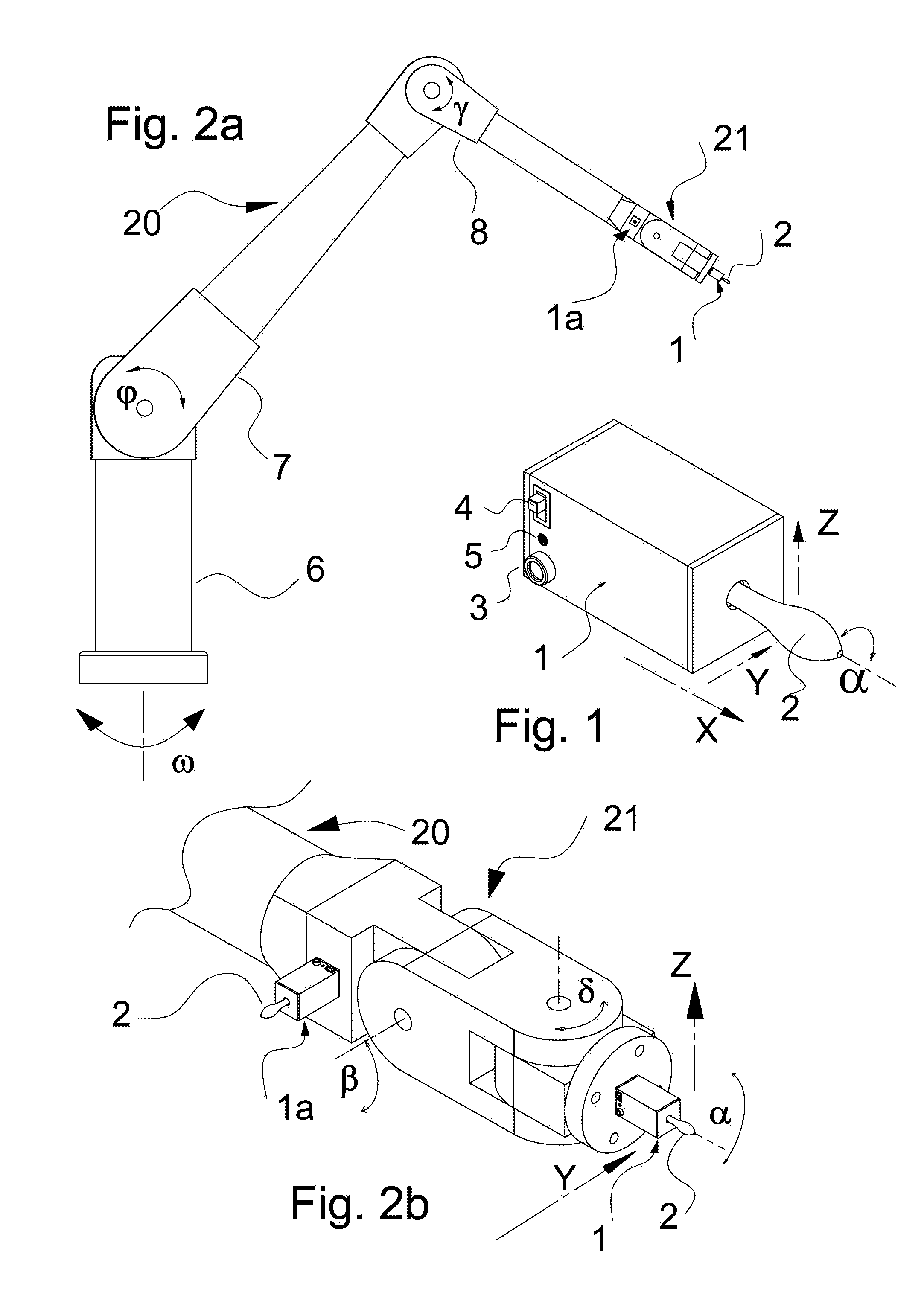
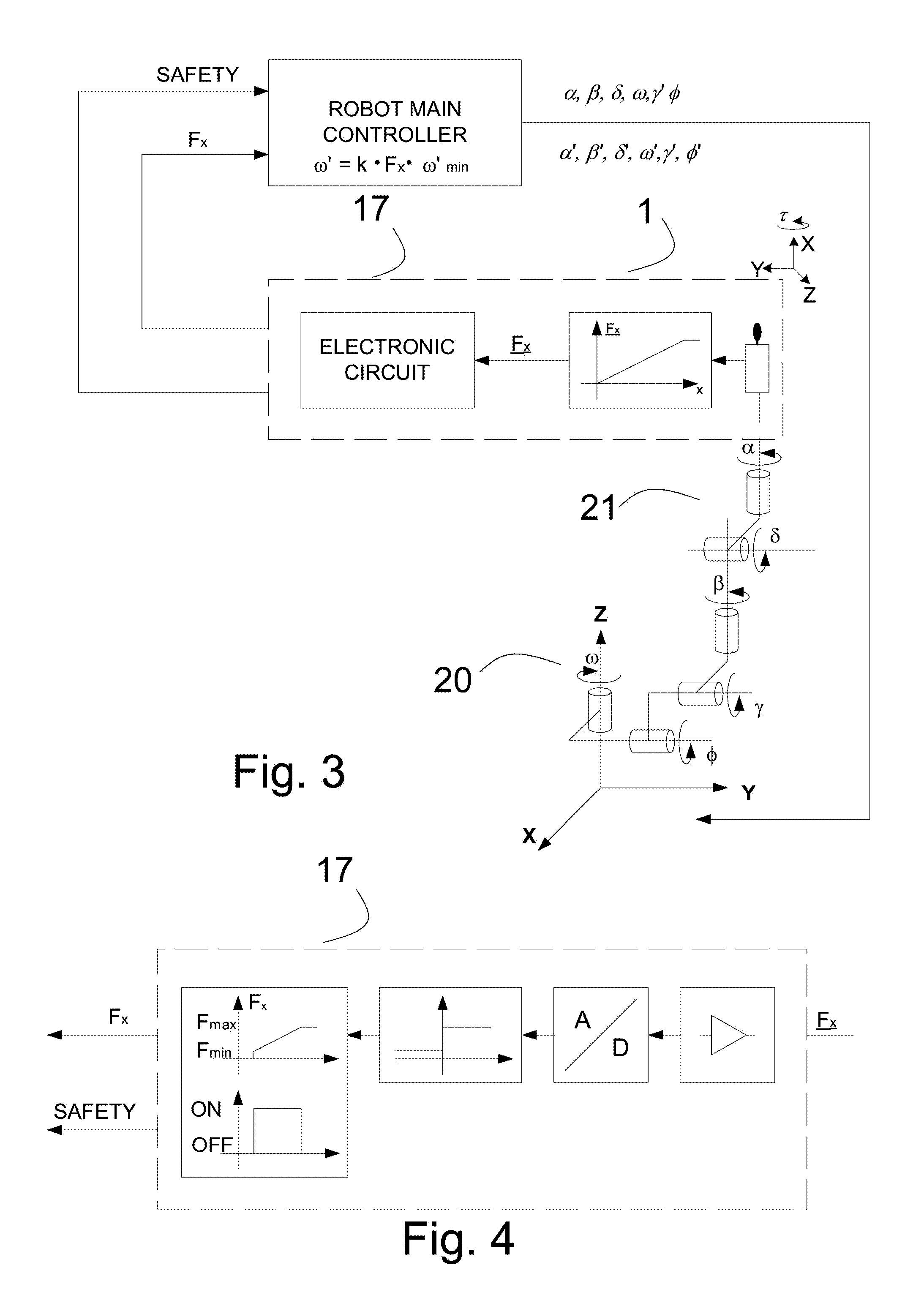
[0034]To achieve this object, this invention provides a four degree of freedom apparatus implementing tactile sensors generating electrical signal corresponding to the force applied to the said sensors. The terms “tactile sensor” or “force sensor” as used herein, generally refer to a device having a touch sensitive surface that can detect contact with another tangible structure, object, entity, or the like. In particular, a touch sensitive surface can indicate not only that the surface is touched but also can provide ...


PUM


Abstract

A method and apparatus are disclosed for the direct and safe teaching of a robot. The apparatus consists of a plurality of tactile sensors and electronic circuitry encapsulated in a compact enclosure, and a handle protruding from the enclosure. The handle provides an easy means for an operator to apply an external force and to act on the sensors that generate electronic signals to the robot controller. The signals, proportional to the applied force, carry information that sets boundaries for safe operations, thus protecting the operator from any harm and the robot from damage.While in the teaching mode the operator guides the robot with the apparatus to the predetermined work positions that are recorded in the controller memory. The work position recording can be handled by either activating a pushbutton or by a voice command. The recorded positions are played back when the robot operates in the work mode.

Description

FIELD OF THE INVENTION[0001]The present invention relates generally to industrial robots and more particularly to a method and an apparatus for teaching robots work positions.BACKGROUND OF THE INVENTION[0002]There are a number of methods and apparatus proposed to perform the robot teach-in operation. They take different approach considering the size of force needed to be applied, operator safety and fatigue during the operation proposing solutions of various complexity and advancement, solving the teaching problem at various completeness levels.[0003]The proposed methods and devices present a number of shortcomings such as complexity, application limited to specific robot configuration, limited safety features or lack of them additionally increasing fatigue of the operator, to list a few.[0004]In a first method, as disclosed in the U.S. Pat. No. 6,212,443, issued to H. Nagata et al., an apparatus with a force detector and a teaching tool is employed to minimize operator's fatigue an...

Claims


Application Information

Patent Timeline
Patent Type & Authority Applications(United States)
IPC IPC(8): B25J9/16B25J19/02B25J9/06
CPCB25J9/106G05B2219/36401G05B19/423B25J13/085
Inventor SZALEK, LESZEK A.
Owner SZALEK LESZEK A
Why Eureka
Try Eureka