
Remote unattended low level light therapy orthopedic device, wearing means and method of use
a low-level light therapy and orthopaedic technology, applied in the field of orthopaedic devices, to achieve the effects of preventing cell death and tissue damage in patients, promoting wound healing, and reducing pain, inflammation and edema
- Summary
- Abstract
- Description
- Claims
- Application Information
AI Technical Summary
Benefits of technology
Problems solved by technology
Method used
Image

Examples
Embodiment Construction
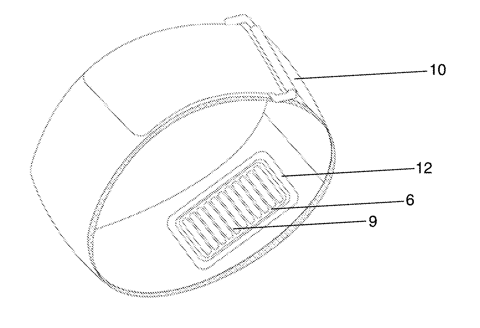
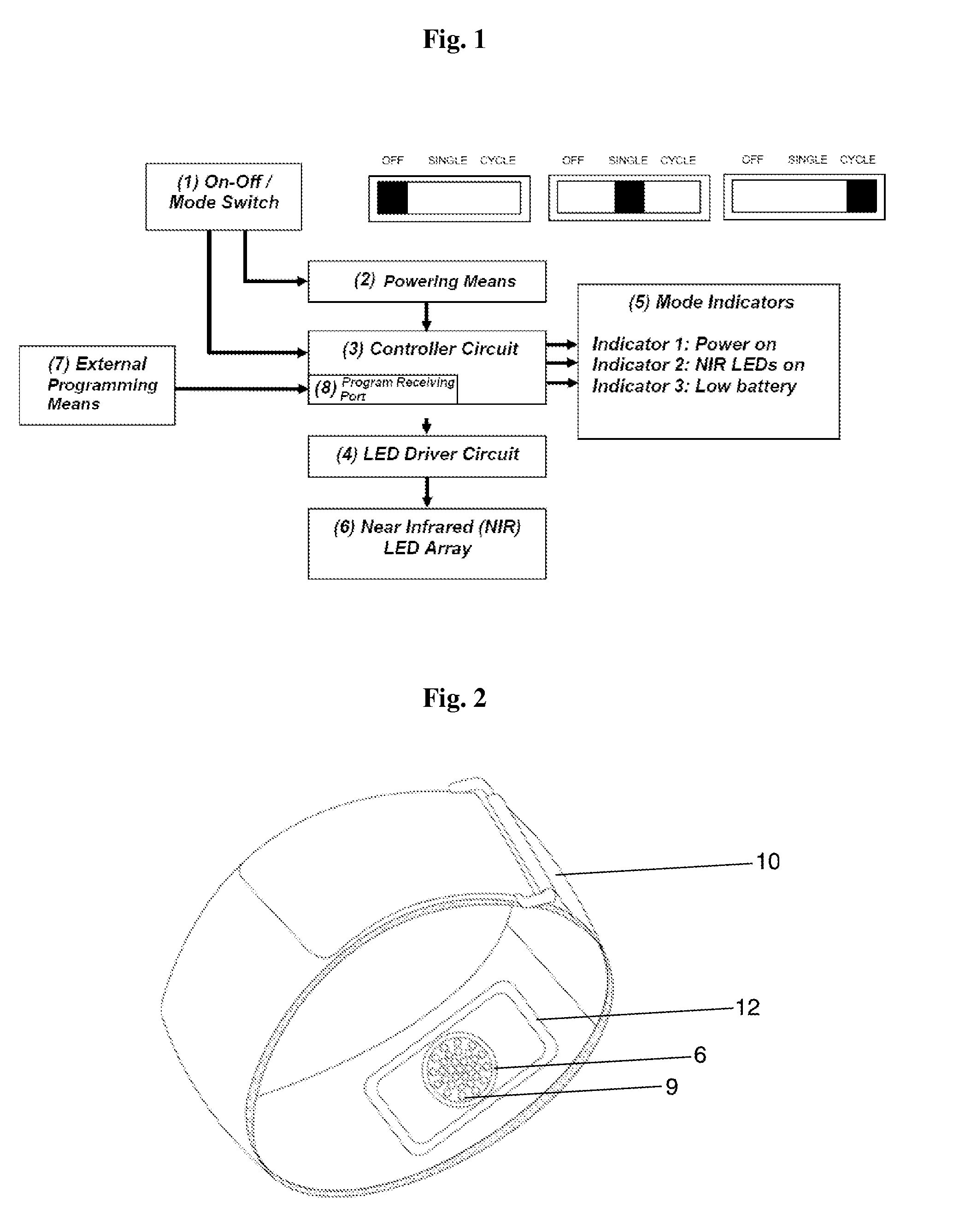
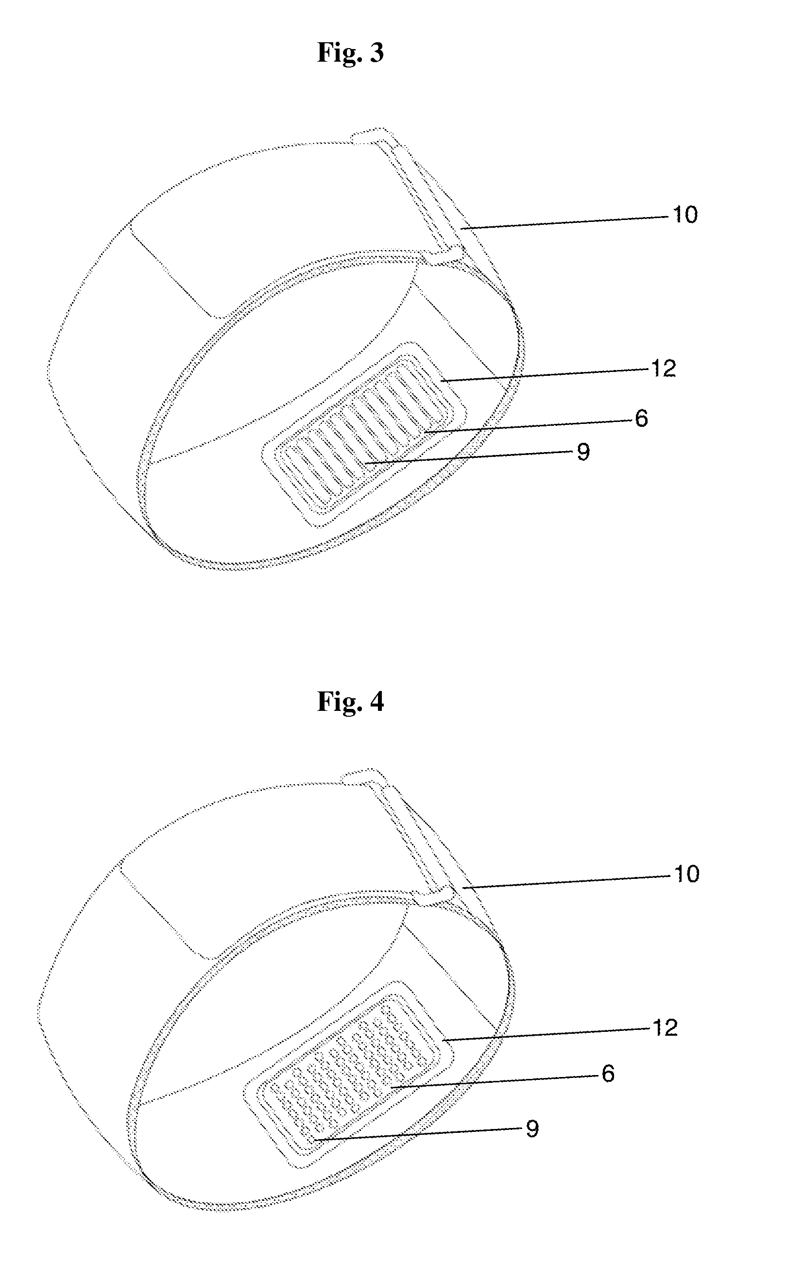
[0029]As described above, the present invention provides a new and useful portable remote unattended low level light therapy orthopedic device which is lightweight, portable, programmable, affordable, able to be worn passively by the patient, able to operate unattended by a practitioner or physician, and can be used to administer multiple and / or extended treatment intervals outside the office setting. The following description and accompanying drawings disclose at least one version of such a device.
[0030]Referring to FIG. 1, an on-off / mode switch 1 serves two functions: (a) it applies power to the device through a powering means 2 which may be a battery, an AC wall adapter type power supply, or combination of the two, and, optionally, (b) the switch 1 determines the mode 140 of operation (single duration or repetitive cycling) of the device. Once power is applied, a microprocessor-based controller circuit 3 cycles a LED driver circuit 4 and a near infrared (NIR) LED array 6, for eit...
PUM
 Abstract
Description
Claims
Application Information