Lancet for blood collection and puncture needle unit

a puncture needle and tongue technology, applied in the field of tongues for blood collection and puncture needle units, can solve the problems of shock, sound, vibration, etc., and achieve the effect of safe easy and convenient and safe disposal of used puncture needles

Active Publication Date: 2010-04-22
PHC HLDG CORP
View PDF5 Cites 102 Cited by
  • Summary
  • Abstract
  • Description
  • Claims
  • Application Information

AI Technical Summary

Benefits of technology

[0006]The present invention is made to solve the above-mentioned problems and has for its object to provide a lancet for blood collection and a puncture needle unit, which are able to reduce pain and fear of a patient due to shock, sound, and vibration when performing puncture using a puncture needle, and prevent the puncture needle from puncturing the same portion a few times, and further, ensure excellent usability and handling ability with safety.

Problems solved by technology

According to this method, shock, sound, and vibration during puncture are considerable.
Further, since the puncture needle vibrates due to the balance of the spring forces, the puncture needle might puncture the same portion or its vicinity a few times. Further, when attaching or detaching the puncture needle to / from the lancet, the needle is unprotected because it is not covered with the protection cap, and the puncture rod easily moves because it is held by only the spring, leading to puncture by mistake.

Method used


Image

  • Lancet for blood collection and puncture needle unit
  • Lancet for blood collection and puncture needle unit
  • Lancet for blood collection and puncture needle unit

Examples


embodiment 1

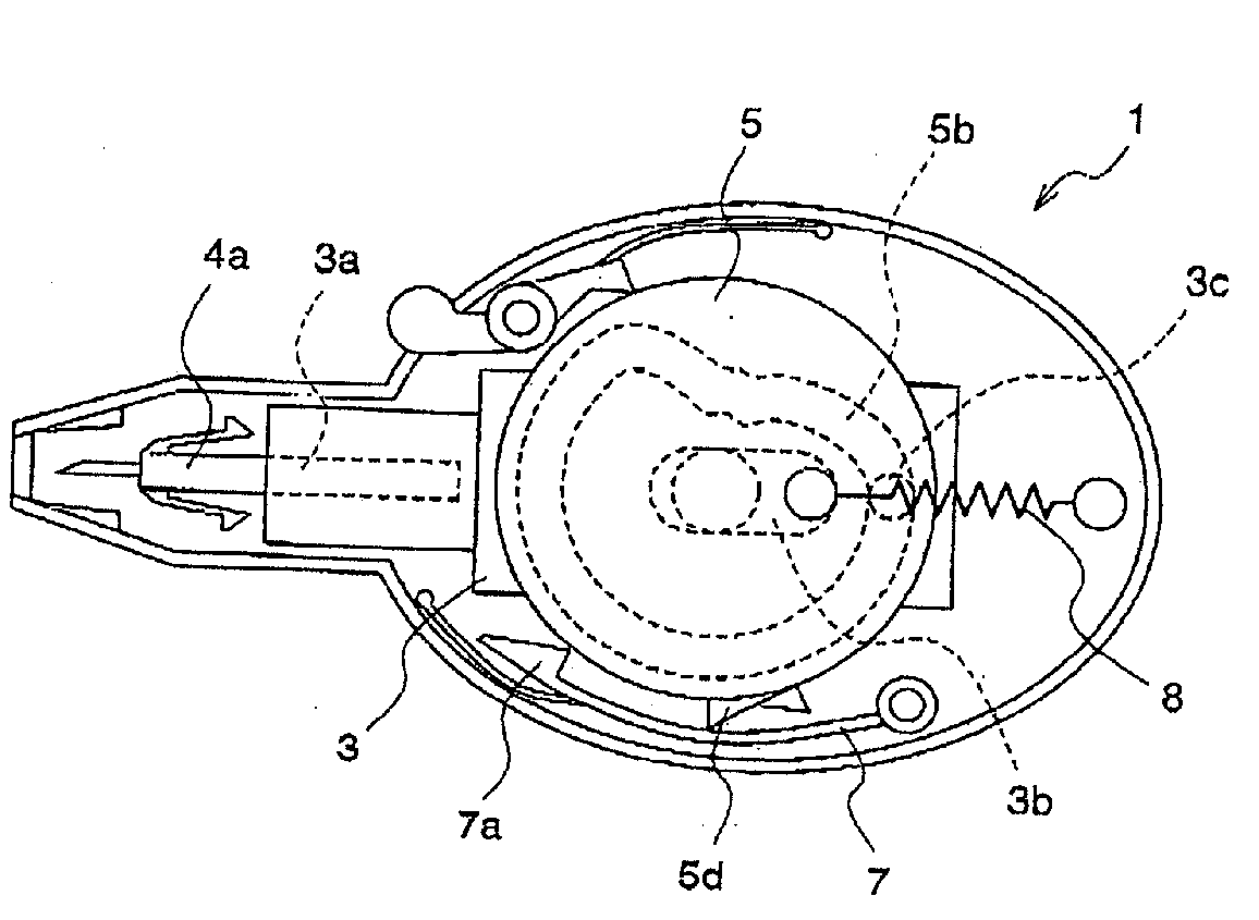
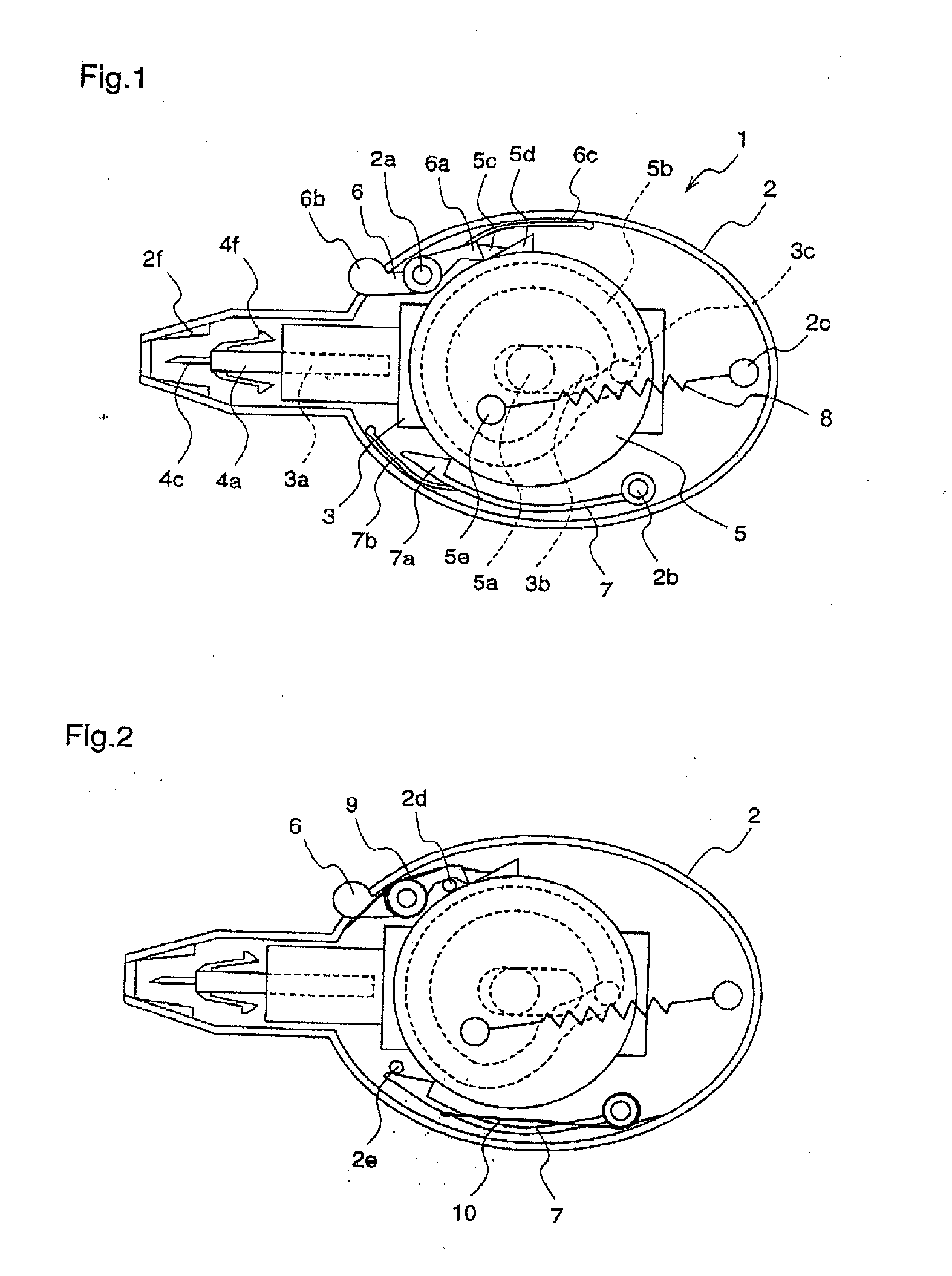
[0058]FIG. 1 is a plane view illustrating a lancet in a puncture-ready state, according to a first embodiment of the present invention.

[0059]In FIG. 1, a lancet body 1 according to the first embodiment has a bottom case 2 as a base, and various kinds of parts are incorporated in the bottom case 2. A slider 3 has a puncture needle fixing hole 3a in which a puncture needle body 4a is inserted, a slide groove 3b that guides the slider 3, and a cam follower 3c to be guided by a cam groove 5b, and the slider 3 is reversibly slidable in the longitudinal direction.

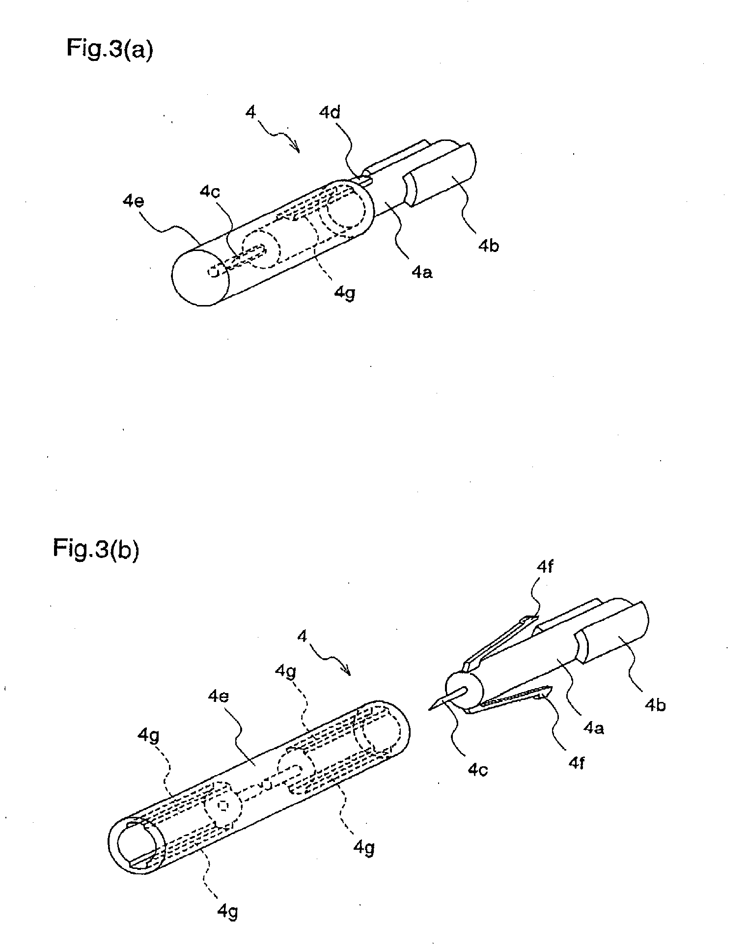
[0060]The puncture needle body 4a has, at an end thereof, a needle 4c that is able to puncture a fingertip or the like, and an elastic safety claw 4f. The puncture needle body 4a is inserted in the puncture needle fixing hole 3a of the slider 3.

[0061]A cam ring 5 is flat in shape, and rotatable about a cam ring support shaft 5a. The cam ring 5 has the continuous cam groove 5b within its rotation plane, and the cam groove 5b guide...

embodiment 2

[0094]FIG. 6 is an external perspective view of a lancet according to a second embodiment of the present invention, FIG. 7 is a cross-sectional view illustrating the internal structure of the lancet, and FIG. 8 is an external perspective view of a puncture needle to be used for the lancet. As in the first embodiment, the lancet and the puncture needle are used to collect a small amount of blood for such as measurement of blood sugar. FIGS. 9(a)-9(c) are diagrams illustrating the procedures for setting the puncture needle into the lancet to perform puncture operation.

[0095]As shown in FIG. 6, a lancet 61 according to the second embodiment is provided with a puncture depth adjustment ring 81 having a puncture needle loading slot 69 at an end, a body top case 62, and a body bottom case 63.

[0096]In the body top case 62 and the body bottom case 63, as shown in FIGS. 7(a) and 7(b), there are provided a slider 64, a link mechanism 79, a flywheel 71, a puncture set lever 68, a stopper arm 7...


PUM


Abstract

A lancet having a slider with a puncture needle holding mechanism at one end thereof, and having a cam ring with a continuous cam groove, rotatable about a support shaft, and with a cam ring claw and an anti-return claw restricting the rotation. The lancet also having a ring spring applying a force to rotate the cam ring, having a rotatable stopper arm holding and releasing the rotation of the cam ring, and having a rotatable ratchet restricting the direction of rotation of the cam ring. A puncture needle unit including a puncture needle body integrally molded with a protrusion fitted to the lancet, a rotation stop rib, a puncture needle, and a puncture needle cap lightly pressed into the puncture needle body.

Description

[0001]The present application is a divisional of U.S. Application Ser. No. 11 / 011,184, filed Dec. 15, 2004.FIELD OF THE INVENTION[0002]The present invention relates to a lancet for blood collection and a puncture needle unit, which are used for measuring blood sugar or the like. More specifically, the invention relates to a technique for performing puncture using the lancet, and a technique for attaching / detaching the puncture needle unit to / from the lancet.BACKGROUND OF THE INVENTION[0003]A conventional lancet will be described with reference to FIG. 13. A disposal puncture needle 127 is attached to a lancet 120, and a fingertip or arm of a patient is punctured with a needle 127A provided at the front end of the puncture needle 127 to collect blood from the punctured portion. The typical lancet 120 comprises a cylindrical body 121, and a cap 126. A slidable puncture rod 123 for holding the puncture needle 127 is incorporated in the body 121, and the puncture rod 123 has a first spr...

Claims


Application Information

Patent Timeline
Patent Type & Authority Applications(United States)
IPC IPC(8): A61B17/32A61B5/00A61B5/15
CPCA61B5/15186A61B5/1411A61B5/150022A61B5/150183A61B5/150435A61B5/150587A61B5/150717A61B5/15113A61B5/15117A61B5/15128A61B5/1519A61B5/15194
Inventor IIO, TOSHIAKIAMANO, YOSHINORIKUROKAWA, KOYASHINOHARA, NORIYUKI
Owner PHC HLDG CORP
Why Eureka
Try Eureka