Eureka AIR delivers breakthrough ideas for toughest innovation challenges, trusted by R&D personnel around the world.

Method For Removing Liquid, And Liquid Operation Device

Active Publication Date: 2018-11-08
OTSUKA PHARM CO LTD
View PDF6 Cites 1 Cited by
  • Summary
  • Abstract
  • Description
  • Claims
  • Application Information

AI Technical Summary

Benefits of technology

[0016]The present invention provides a method for removing a liquid in a channel of a channel chip, the method being capable of reducing the amount of a residual

Problems solved by technology

Then, it is difficult to completely remove the liquid in the channel, and some of the liquid may be left unremoved in the channel (hereinafter, a liquid left unremoved is also simply referred to as “residual liquid”).
If a liquid subse

Method used


Image

  • Method For Removing Liquid, And Liquid Operation Device
  • Method For Removing Liquid, And Liquid Operation Device
  • Method For Removing Liquid, And Liquid Operation Device

Examples


Example

Embodiment 1

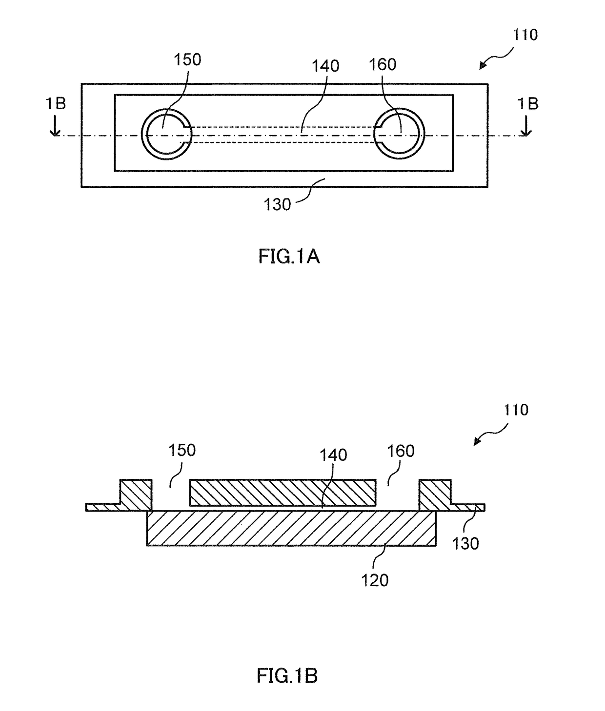
[0047]Embodiment 1 relates to a method for removing a liquid in the inside of channel chip 110 by suction of the liquid in the inside of channel chip 110 into the inside of a liquid suction instrument (pipette 210) inserted into through-hole 150.

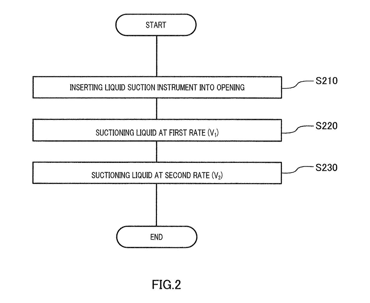
[0048]FIG. 2 is a flowchart for the method for removing a liquid in Embodiment 1. The removal method according to the present embodiment includes suction of a liquid at a first rate (hereinafter, also simply represented as “V1”) (S220) and suction of a liquid performed sequentially thereafter at a second rate (hereinafter, also simply represented as “V2”) lower than V1 (S230). The removal method according to the present embodiment may further include insertion of a liquid suction instrument (pipette 210) into through-hole 150 (S210).

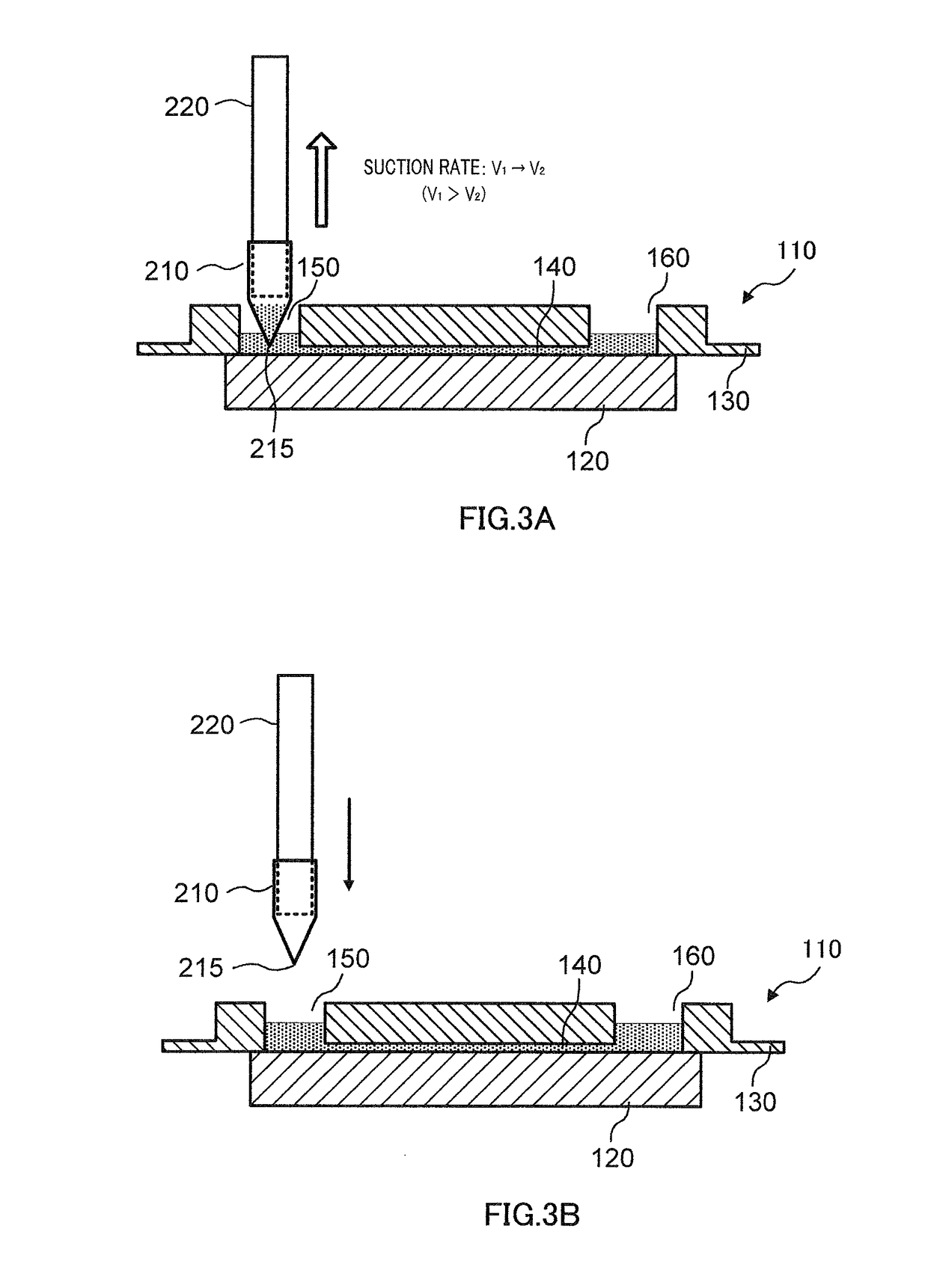
[0049]FIG. 3A is a cross-sectional view illustrating one example of modes of liquid removal in Embodiment 1. In FIG. 3A, the liquid suction instrument includes, for example, pipette 210 and nozzle 220...

Example

Embodiment 2

[0061]Embodiment 2 relates to a method for removing a liquid in which suctioning at a first rate (S220) in Embodiment 1 is performed only when the surface of the liquid in through-hole 160 or liquid reservoir 170 is higher than ceiling 145 of channel 140. The other components are the same as those of Embodiment 1, and hence redundant descriptions will be omitted.

[0062]FIGS. 4A and 4B are each a cross-sectional view illustrating one example of modes of liquid removal in Embodiment 2. In the present embodiment, suctioning at a first rate V1 (S220) is performed only when the surface of the liquid is higher in the vertical direction than ceiling 145 of channel 140. In other words, any of suctioning at a first rate V1 (S220) and suctioning at a second rate V2 (S230) may be performed when the surface of the liquid is higher in the vertical direction than ceiling 145 of channel 140, and suctioning at a second rate V2 (S230) is performed, without performing suctioning at a first...

Example

Embodiment 3

[0066]Embodiment 3 relates to a method for removing a liquid in channel 140 in which suction of the liquid at a second rate (V2) (S230) in Embodiment 1 or Embodiment 2 is performed and sequentially thereafter suction of the liquid at a third rate (V3) lower than the second rate (S240) is performed. The suctioning at a third rate (S240) is performed when the surface of the liquid is within channel 140. The other components are the same as those of Embodiment 1 or Embodiment 2, and hence redundant descriptions will be omitted.

[0067]FIG. 5 is a flowchart for a method for removing a liquid in Embodiment 3. FIGS. 6A and 6B are cross-sectional views illustrating different examples of modes of liquid removal in S240 added in the present embodiment.

[0068]S240 is a step in which the liquid is suctioned into the liquid suction instrument at a suction rate from pipette 210 of a third rate (hereinafter, also simply represented as “V3”) lower than the second rate. V3 is only required...


PUM


Abstract

The present invention provides a method for removing liquid from the interior of a flow channel tip, which enables both to reduce the amount of liquid remaining and prevent the time spent removing the liquid from being longer than necessary. The method comprises: suctioning a liquid within a flow channel, the liquid being suctioned into the interior of a liquid suction implement inserted into a first through-hole of a flow channel tip; and removing the liquid within the flow channel This method comprises: a first suction step for suctioning some of the liquid within the flow channel at a first suction speed; and a second suction step for suctioning the liquid remaining within the flow channel at a second suction speed that is less than the first suction speed, the second suction step being performed in continuation from the first suction step.

Description

TECHNICAL FIELD[0001]The present invention relates to a method for removing a liquid in a channel of a channel chip by suction, and a liquid-manipulating apparatus for implementing the method.BACKGROUND ART[0002]Known is a technique using a small chip provided with a channel (hereinafter, also simply referred to as “channel chip”) to allow a liquid to move in the channel for reaction between substances contained in the liquid, separation of a substance from the liquid, detection of a substance contained in the liquid, or mixing of liquids (hereinafter, also referred to as simply “reaction or the like”). The channel chip includes a channel as a place for the reaction or the like, and a plurality of through-holes each allowing the channel to communicate with the outside of the channel The channel chip enables reaction or the like in a simple and quick manner, and thus is under active development in recent years.[0003]A liquid for reaction or the like is introduced into the channel via...

Claims


Application Information

Patent Timeline
IPC IPC(8): G01N35/10
CPCG01N35/1004G01N37/00G01N35/1009G01N35/1016G01N2035/00237G01N2035/0437G01N2035/1034G01N21/648
Inventor IWASHITA, ATSUOAOKI, YOUICHIMIYAZAKI, KOJI
Owner OTSUKA PHARM CO LTD
Why Eureka
Eureka Blog
Learn More