
Vehicle control apparatus

Active Publication Date: 2018-11-15
TOYOTA JIDOSHA KK
View PDF0 Cites 0 Cited by
  • Summary
  • Abstract
  • Description
  • Claims
  • Application Information

AI Technical Summary

Benefits of technology

The present invention aims to prevent the engine stall while driving on a downhill road, which can make it hard to stop the vehicle. The invention does not affect the shifting between forward and reverse gears on a flat road, ensuring operational convenience for drivers. The technical effect is to enhance operational safety and convenience for drivers on both flat and downhill roads.

Problems solved by technology

However, even at a low running speed of a vehicle at which an engine stop (i.e., an engine stall) does not occur on a flat road, when the switching between the forward drive range and the reverse drive range is made on a downhill road, a larger inertia of the vehicle is generated, as compared with on a flat road, so that a larger torque inputted to the engine is generated on the downhill road whereby an engine stall could occur.
The occurrence of the engine stall causes a vacuum pressure in an intake of the engine to be reduced, and accordingly reduces a force which is generated by a brake booster using the vacuum pressure and which assists a brake pedal force (i.e., force applied to depress a brake pedal of the vehicle), thereby resulting in a situation in which the vehicle cannot be stopped easily.
Further, in an arrangement in which the above-described given value is reduced for inhibiting the shift range switching even at a lower running speed of the vehicle for preventing the engine stall also on a downhill road, there is a risk that the operational convenience is impaired, for example, in “going back and forth”, because of more limitation on the shift range switching between the forward drive range and the reverse drive range even on a flat road.

Method used


Image

  • Vehicle control apparatus
  • Vehicle control apparatus
  • Vehicle control apparatus

Examples


first embodiment

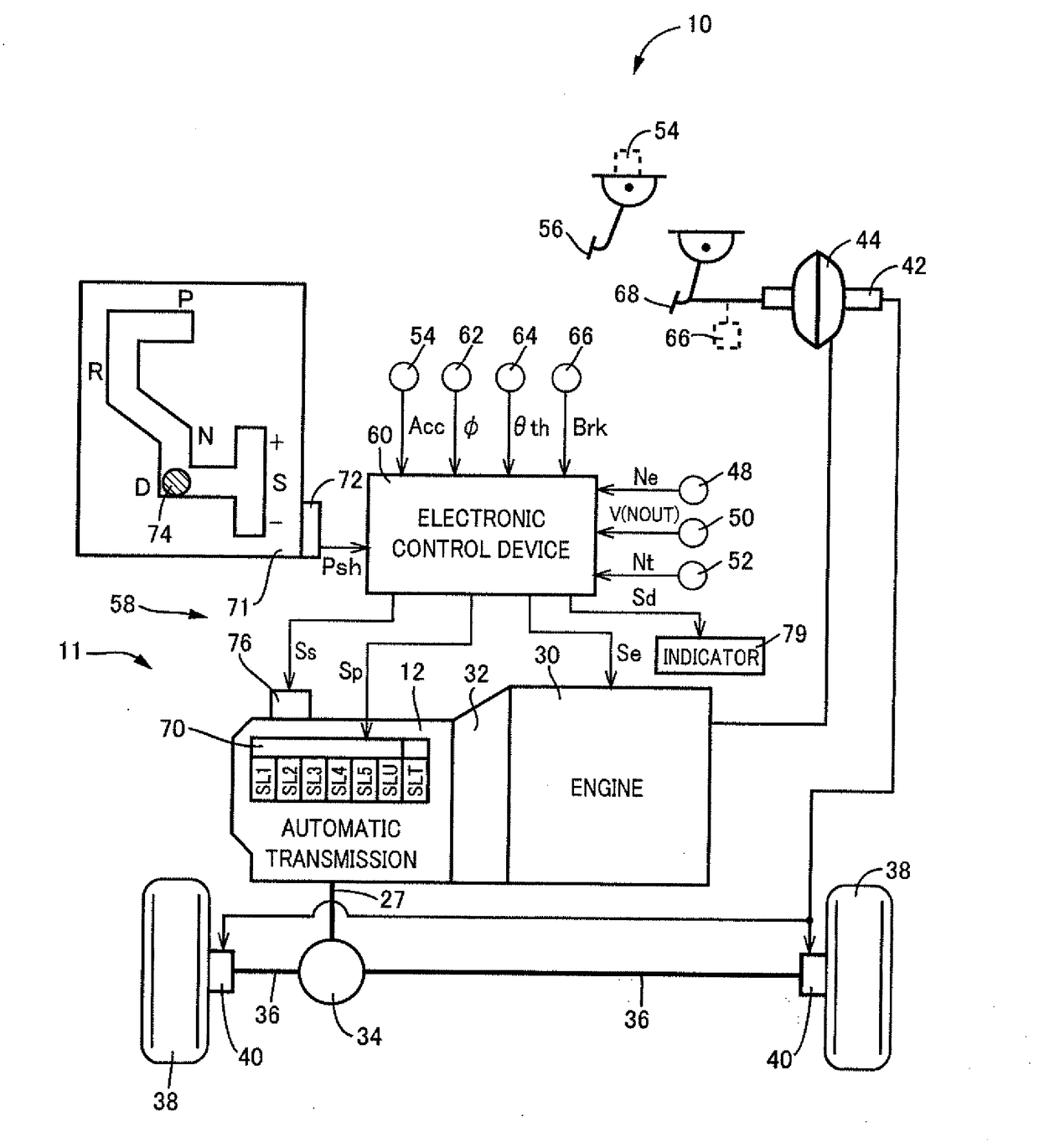
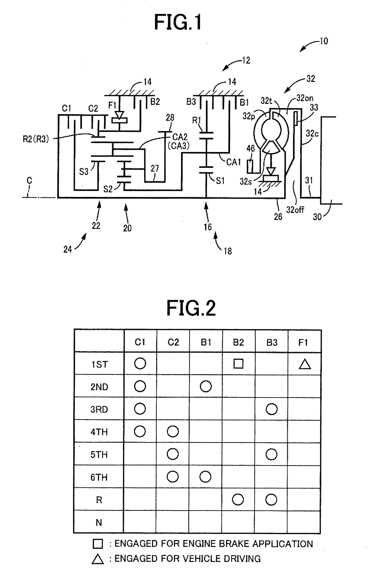
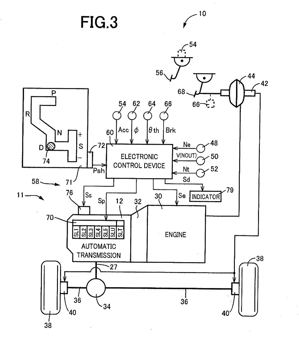
[0029]FIG. 1 is a schematic view showing a construction of an automatic transmission 12 of a vehicle 10, which is to be controlled by an electronic control device 60 serving as a control apparatus according to the present invention. This automatic transmission 12 is suitably used for an FF vehicle, and is installed in the lateral (transverse) direction of the vehicle 10. The automatic transmission 12 includes a first transmission portion 18 and a second transmission portion 24 which are disposed coaxially with each other on a common axis C and which are disposed in a transaxle casing 14 as a non-rotatable member that is attached to a body of the vehicle 10. The first transmission portion 18 is principally constituted by a first planetary gear set 16 of a single-pinion type, while the second transmission portion 24 is a transmission device of a Ravigneaux type which is principally constituted by a second planetary gear set 20 of a double-pinion type and a third planetary gear set 22 ...

second embodiment

[0054]In the above-described first embodiment, in the vehicle 10 is provided with the automatic transmission 12 and the shifting device 58 configured to establish a shift range in the automatic transmission 12 by operation of the shift actuator 76, such that the established shift range corresponds to the shift-lever operating position of the shift lever 74, the switching request requesting the automatic transmission 12 to be switched to the opposite-direction drive range (for driving the vehicle 10 in a direction opposite to the current running direction) is rejected in a case when the vehicle running speed V is not lower than the threshold value (given value) Va and also in a case when the vehicle 10 runs on a downhill road even if the running speed V of the vehicle is lower than the threshold value Va. In the second embodiment, in either of the above-described cases, in addition to the rejection of the switching request requesting switching to the opposite-direction drive range, t...

third embodiment

[0065]In the above-described embodiments, the shift operation device 71 shown in FIG. 3 is of alternate type in which the shift lever 74 is kept in one of the shift-lever operating positions after an operator's operation for placing the shift lever 74 in the one of the shift-lever operating positions. However, the shift operation device 71 is may be replaced by a momentary-type shift operation device 94, as shown in FIG. 9, in which the shift lever 74 is automatically returned to a predetermined home position after the shift lever 74 is released from operation by the operator. In an example shown in FIG. 9, the shift operation device 94, which is defined by broken line, is constituted by the shift lever 74 and a P switch 96. The shift operation device 94 is disposed near the operator's seat, and is provided with the shift lever 74 of momentary type, which is to be practically or functionally placed in a selected one of the plurality of shift-lever operating positions. That is, in th...


PUM


Abstract

A control apparatus for a vehicle provided with (a) a transmission and (b) a shifting device including (b-1) a shift actuator and (b-2) a shift lever. The shift actuator establishes one of shift ranges in the transmission such that the established one of the shift ranges corresponds to a selected one of shift-lever operating positions of the shift lever. When a switching request is made to request the transmission to be switched to an opposite-direction drive range that is for driving the vehicle in a direction opposite to a current running direction of the vehicle, during running of the vehicle with a speed being not lower than a given value, the control apparatus rejects the switching request. The control apparatus rejects the switching request, also during running of the vehicle with the running speed being lower than the given value, if the vehicle is running on a downhill road.

Description

[0001]This application claims priority from Japanese Patent Application No. 2017-095981 filed on May 12, 2017, the disclosure of which is herein incorporated by reference in its entirety.FIELD OF THE INVENTION[0002]The present invention relates to a technique for restraining an engine stall even when a drive range for driving in a direction opposite to a current running direction is selected by a vehicle operator during running on a downhill road.BACKGROUND OF THE INVENTION[0003]There is well known an automatic transmission with a plurality of shift ranges in which switching from a forward drive range as one of the shift ranges to a reverse drive range as one of the shift ranges is inhibited during a forward running. For example, JP-2003-166643A discloses a vehicle control apparatus configured to inhibit switching from the forward drive range to the reverse drive range by operation of an operator of a vehicle when the vehicle runs at a speed not lower than a given value, and to allo...

Claims


Application Information

Patent Timeline
IPC IPC(8): B60W30/188B60W50/08B60W50/14
CPCB60W30/1884B60W50/087B60W50/14B60W2520/10B60W2540/00B60W2710/0677B60W2550/142F16H59/44F16H59/66F16H61/18F16H2059/663F16H2061/185F16H2061/165F16H61/16F16H3/663F16H2200/0052F16H2200/2007F16H2200/2023F16H2200/2043F16H2200/2066F16H2200/2082B60W2552/15
Inventor SHINE, KAZUMIYAMADA, KAZUHIKO
Owner TOYOTA JIDOSHA KK
Learn More