Method of Building Tire and Tire Building Machine

Active Publication Date: 2018-11-29
YOKOHAMA RUBBER CO LTD
View PDF4 Cites 1 Cited by
  • Summary
  • Abstract
  • Description
  • Claims
  • Application Information

AI Technical Summary

Benefits of technology

[0007]According to the present technology, the inner circumferential surfaces of the projecting parts at the longitudinal direction end portions of the outer circumferential side strip-shaped rubber member, that project in the drum width direction relative to the inner circumferential side strip-shaped rubber member and are in a floating state, are supported so as to be positioned at the level of the outer circumferential surface of the inner circumferent

Problems solved by technology

When layering a member such as a rubber chafer member on an innerliner member already wrapped on a building drum with the rubber chafer member projecting in the drum width direction, and then bonding longitudinal direction end surfaces of the members to each other, it is easy for the bonding position to become skewed, and difficult to bond

Method used


Image

  • Method of Building Tire and Tire Building Machine
  • Method of Building Tire and Tire Building Machine
  • Method of Building Tire and Tire Building Machine

Examples


Embodiment Construction

[0026]A method of building a tire and a tire building machine of the present technology will be described on the basis of the embodiments illustrated in the diagrams as follows.

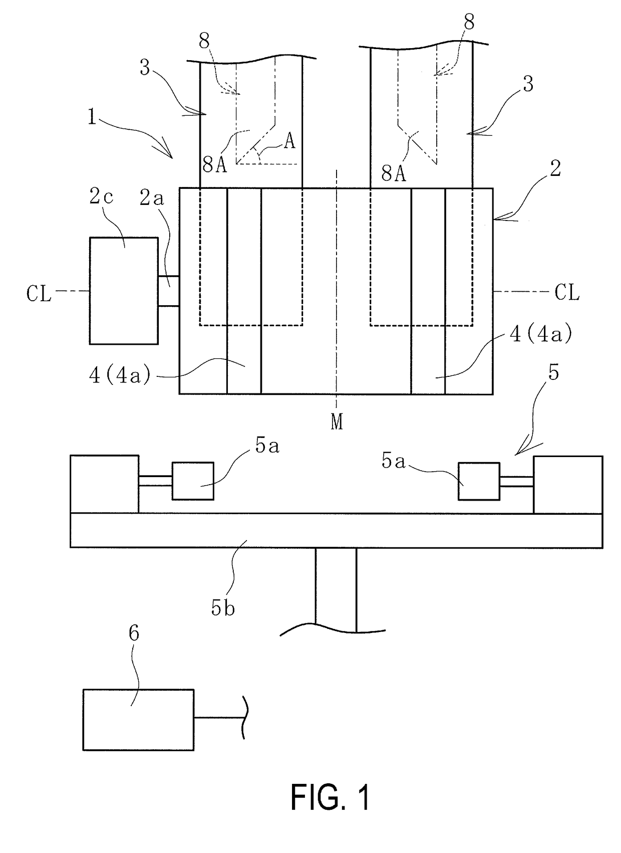
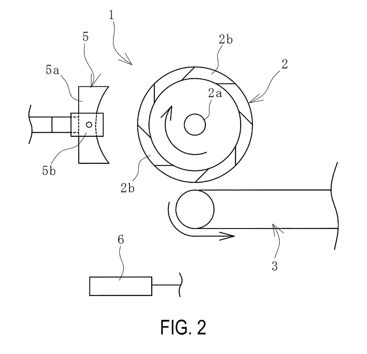
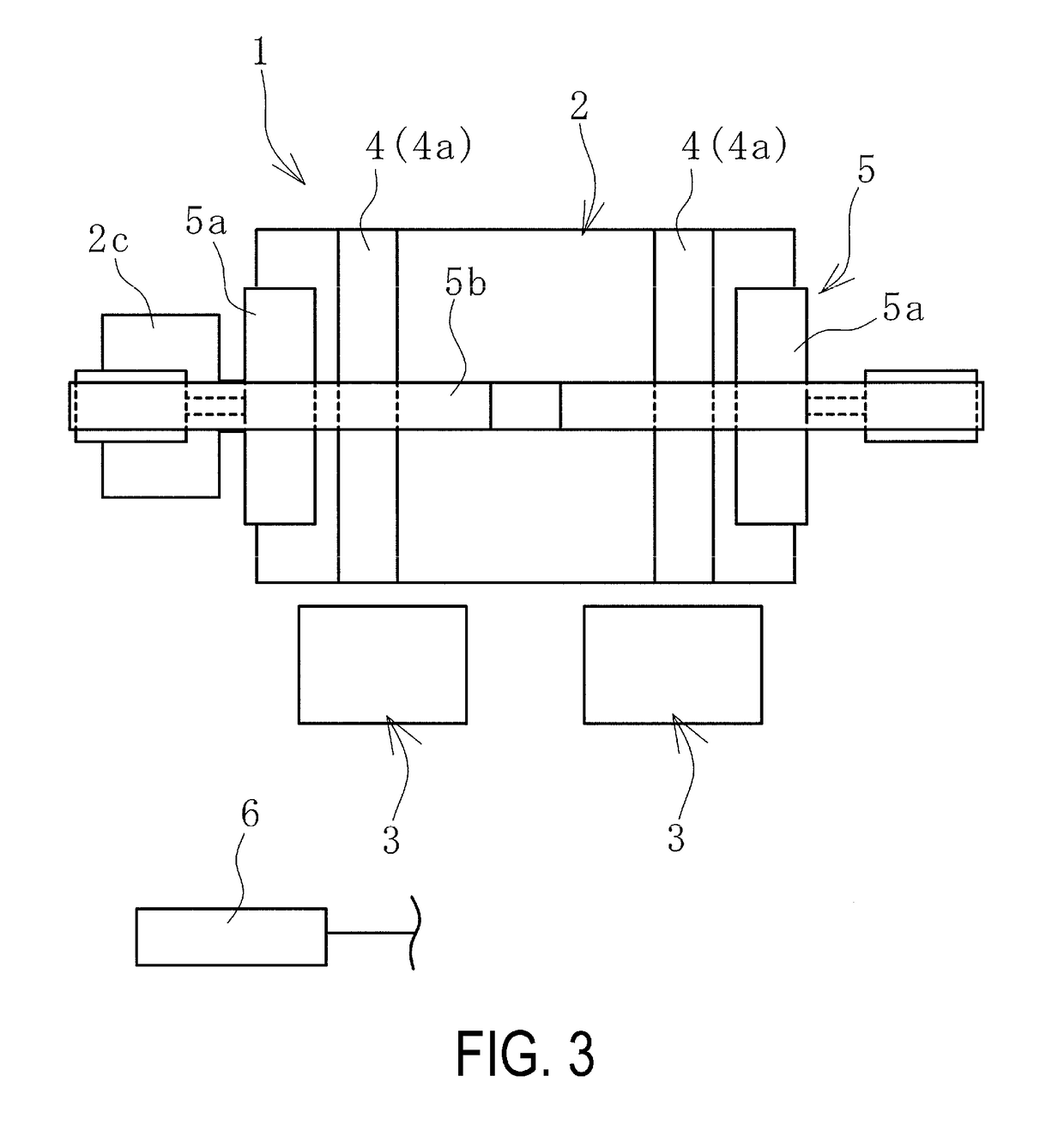
[0027]A tire building machine 1 according to the present technology, illustrated in FIGS. 1 to 3, is used when forming strip-shaped rubber members into a cylindrical shape. As will be described below, in this embodiment, an inner circumferential side strip-shaped rubber member 7 and outer circumferential side strip-shaped rubber members 8 are used as the strip-shaped rubber members. The strip-shaped rubber members 7 and 8 may be constituted of unvulcanized rubber, or may be constituted of unvulcanized rubber and reinforcing wire or the like. In the drawings, a dot-dash line CL indicates a center axis of a building drum 2, and a dot-dash line M indicates a center of the building drum 2 in a width direction thereof. In FIG. 1, the outer circumferential side strip-shaped rubber members 8 are indicated by double-...


PUM


Abstract

The present technology provides a method of building a tire and a tire building machine. When bonding together longitudinal direction end portions of an outer circumferential side strip-shaped rubber member wrapped around a building drum to form a cylindrical shape, inner circumferential surfaces of projecting parts of the longitudinal direction end portions that project in a drum width direction relative to an inner circumferential side strip-shaped rubber member are supported by a support section, and the inner circumferential surfaces are positioned at a level of an outer circumferential surface of the inner circumferential side strip-shaped rubber member. In this state, the projecting parts are pressed in the drum width direction by a pressing section, and the longitudinal direction end portions are bonded together.

Description

TECHNICAL FIELD[0001]The present technology relates to a method of building a tire and a tire building machine. More particularly, the present technology relates to a method of building a tire and a tire building machine that, when an outer circumferential side strip-shaped rubber member wrapped around an relatively outer circumferential side of a building drum is layered on an inner circumferential side strip-shaped rubber member wrapped around an relatively inner circumferential side of the building drum such that the outer circumferential side strip-shaped rubber member projects in a drum width direction, and longitudinal direction end portions of the outer circumferential side strip-shaped rubber member are bonded together to form a cylindrical shape, can suppress skew in the bonding position and enable the longitudinal direction end portions to be strongly bonded together.BACKGROUND ART[0002]When producing a tire, various strip-shaped rubber members are wrapped around a buildin...

Claims


Application Information

Patent Timeline
IPC IPC(8): B29D30/26
CPCB29D30/2607B29D30/28B29D30/3007
Inventor YAMAMURA, EIJIKUMAZAWA, TOMOHIRO
Owner YOKOHAMA RUBBER CO LTD
Why Eureka
Try Eureka