
Water temperature detection valve

Active Publication Date: 2018-11-29
XIAMEN INNO TECH CO LTD
View PDF0 Cites 1 Cited by
  • Summary
  • Abstract
  • Description
  • Claims
  • Application Information

AI Technical Summary

Benefits of technology

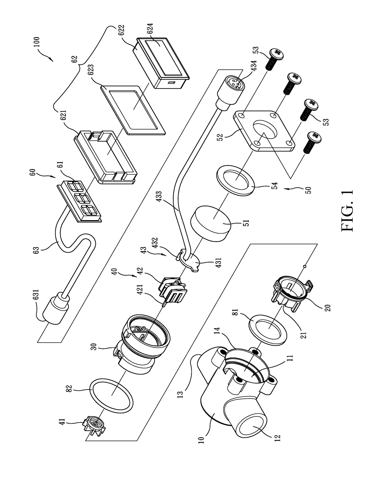
[0003]In view of the above, to improve the deficiencies of the prior art that the conventional water temperature detection device can only be installed on a water dispense device or a pipe that is located outside a wall, the present invention provides a water temperature detection valve, which generally comprises: an external housing, which is formed, in an interior thereof, with a compartment and comprises, formed therein, a water inlet opening formed thereon to communicate between the compartment and outside, a water outlet opening communicating between the compartment and the outside, and an installation hole communicating between the compartment and the outside; a rear water guide, which is arranged in the compartment of the external housing and comprises a plurality of water guide holes communicating between interior and exterior the rear water guide; a front water guide, which is arranged in the compartment of the external housing, the front water guide having a rear end coupled to a front end of the rear water guide, the front water guide comprising a water discharge hole communicating between interior and exterior of the front water guide, the water discharge hole being in communication with the water guide holes and the water outlet opening; a water temperature detection module, which is arranged in the interiors of the rear water guide and the front water guide to generate electrical power and to conduct detection of temperature of water inside the water discharge hole and comprises a blade wheel, a miniature electrical gener

Problems solved by technology

This makes it only installable on a water dispense device that is located externally of a wall.
For water pipin

Method used


Image

  • Water temperature detection valve
  • Water temperature detection valve
  • Water temperature detection valve

Examples


Example

[0014]The following descriptions are exemplary embodiments only, and are not intended to limit the scope, applicability or configuration of the invention in any way. Rather, the following description provides a convenient illustration for implementing exemplary embodiments of the invention. Various changes to the described embodiments may be made in the function and arrangement of the elements described without departing from the scope of the invention as set forth in the appended claims.

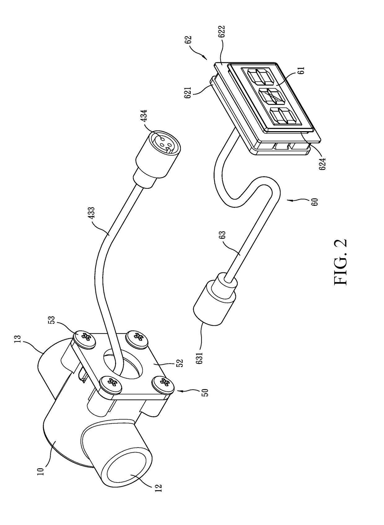
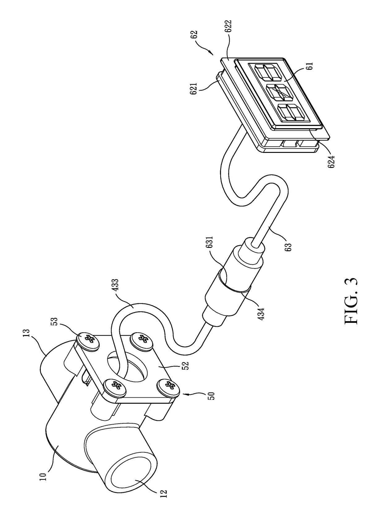
[0015]Referring to FIGS. 1-4, a water temperature detection valve 100 according to a preferred embodiment of the present invention generally comprises an external housing 10, a rear water guide 20, a front water guide 30, a water temperature detection module 40, a closure cover 50, and a water temperature display module 60.

[0016]Referring to FIGS. 1-4, the external housing 10 is formed, in an interior thereof, with a compartment 11 and comprises, formed therein, a water inlet opening 12 formed there...


PUM


Abstract

A water temperature detection valve includes an external housing in which a rear water guide and a front water guide are arranged to respectively receive and retain a blade wheel and an electrical generator, which are movable in unison with each other, to arranged therein. A temperature detection unit includes a circuit board, a temperature sensor electrically connected to the circuit board, and an electrical output cable having an end electrically connected to the circuit board. The circuit board is electrically connected to the electrical generator. The electrical output cable extends outside the external housing. A water temperature display module includes a display device arranged inside a display holder that includes a light-transmitting window corresponding, in position, to the display device. An electrical input cable that is electrically connected to the display device has an end that is connectable, in a detachable manner, to the electrical output cable.

Description

(a) TECHNICAL FIELD OF THE INVENTION[0001]The present invention relates generally to kitchen and bathroom equipment, and more particularly to a water temperature detection valve.(b) DESCRIPTION OF THE PRIOR ART[0002]Bathrooms and kitchens are areas of a building where the skins of human being may get contact with hot water most frequently. To avoid burning of the skins of human bodies by the hot water, it is common to add a device that detects and displays water temperature on a water dispense device. However, such a device is generally structured such that a detection part and a display part are combined together. This makes it only installable on a water dispense device that is located externally of a wall. For water piping or water conveyance device that is located internally of or embedded in a wall, such a device is not usable.SUMMARY OF THE INVENTION[0003]In view of the above, to improve the deficiencies of the prior art that the conventional water temperature detection device...

Claims


Application Information

Patent Timeline
IPC IPC(8): G01K13/02
CPCG01K13/02G01K2013/026E03C2001/0418E03C1/04E03C1/041G01K13/026
Inventor TSAI, PI KUANG
Owner XIAMEN INNO TECH CO LTD
Learn More