System and method for straightening and/or supporting a wall

Active Publication Date: 2016-08-23
POWER BRACE
View PDF60 Cites 13 Cited by
  • Summary
  • Abstract
  • Description
  • Claims
  • Application Information

AI Technical Summary

Benefits of technology

The present invention is a wall reinforcement system that can be installed without disrupting lawn or landscape. The system maximizes space inside the wall and is aesthetically pleasing. It also helps straighten and support parts of the wall, reducing stress and supporting horizontal and vertical loads.

Problems solved by technology

As a result, upon exposure to excessive lateral forces, foundation walls often crack, bow, push inward, or even collapse.
The foundation reinforcement systems commonly known in the art are deficient for a variety reasons.
For example, wall anchoring systems counteract soil pressure by anchoring walls to stable, undisturbed soil outside the wall, which often requires significant excavation of surrounding earth.
Further, given the varying types of soils outside of the wall, such systems are prone to failure.
Many indoor foundation reinforcement systems occupy a large amount of interior space.
For example, braces extending diagonally from the floor to the foundation wall significantly limit interior space of a room proximate to the foundation wall, often limiting overall function and enjoyment of the room.

Method used


Image

  • System and method for straightening and/or supporting a wall
  • System and method for straightening and/or supporting a wall
  • System and method for straightening and/or supporting a wall

Examples


Embodiment Construction

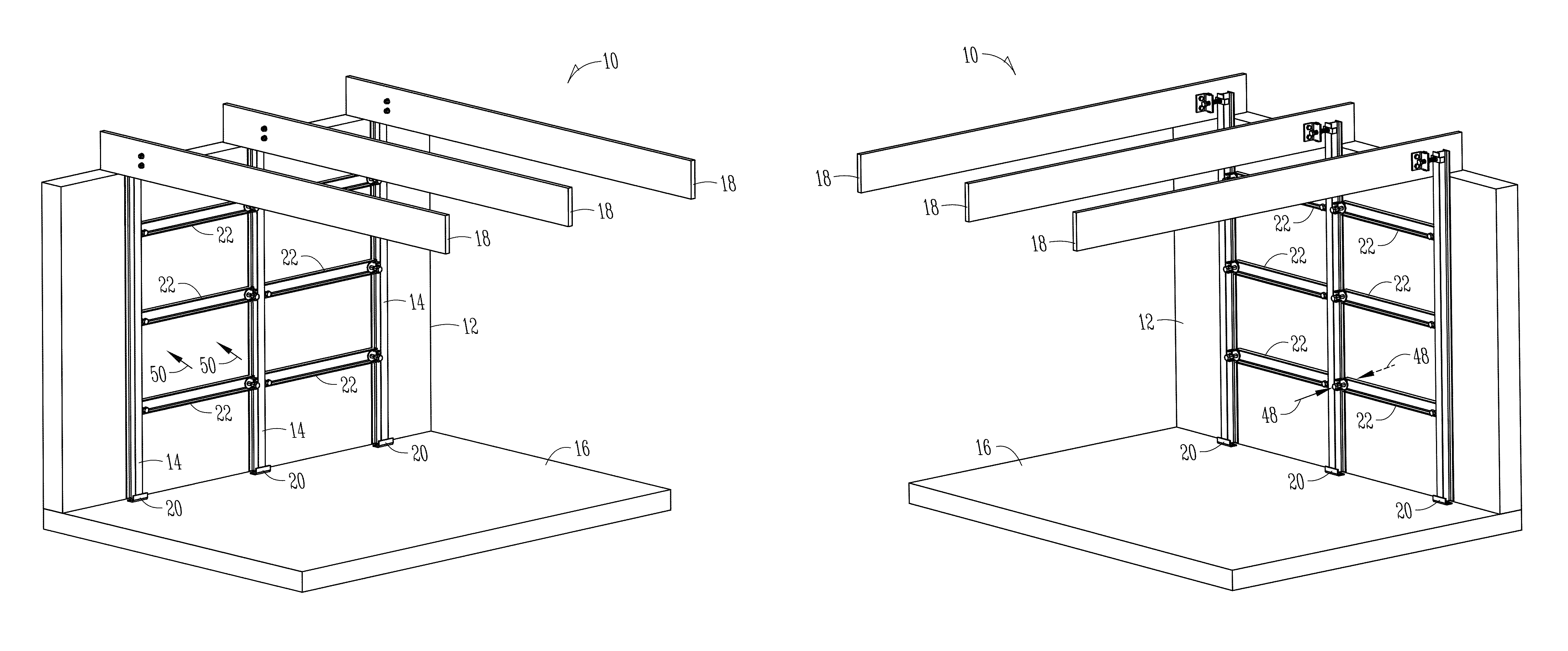
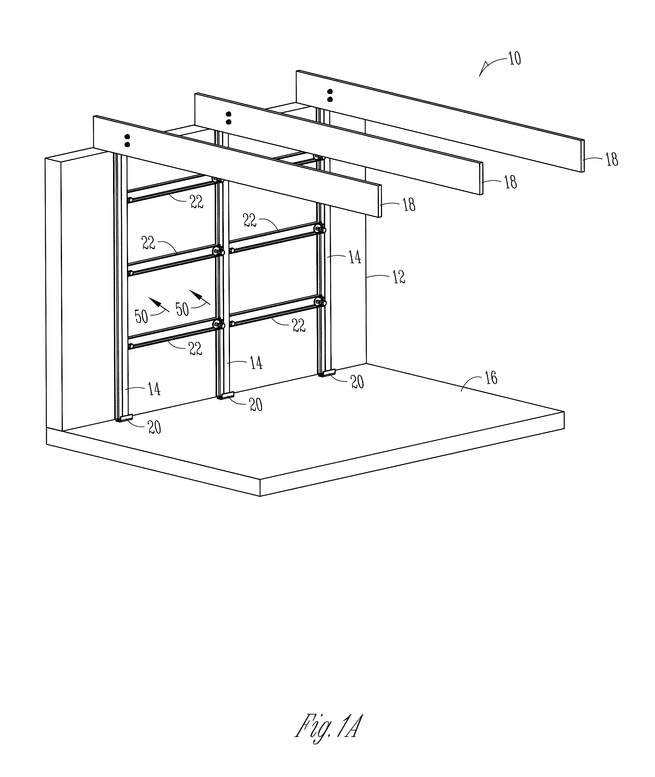
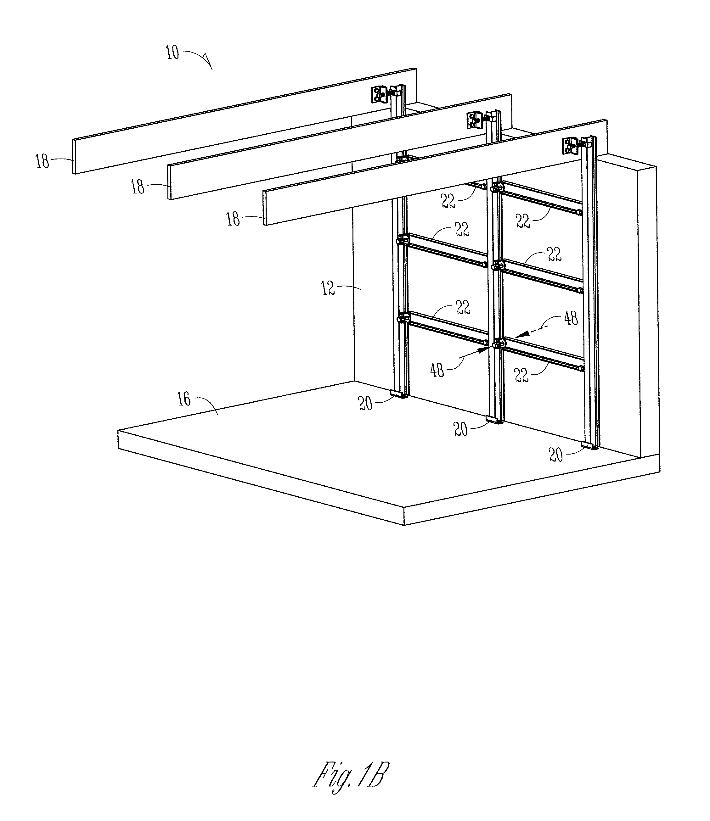
[0033]FIGS. 1A, 1B and 1C illustrate an exemplary wall reinforcement system 10. The system 10 is designed to support and / or straighten a wall 12. The system 10 is comprised of elongated vertical members 14 extending between a floor 16 and a ceiling structure 18. In an exemplary embodiment, the wall 12 and floor 15 comprise a basement foundation wall and floor, respectively. The ceiling structure 18 can comprise floor joists disposed below a main floor of a home. The present disclosure contemplates that the wall reinforcement system 10 can be installed with any type of interior or exterior walls of residential buildings, commercial building, and the like, as well as other types of planar surfaces having means to connect the elongated vertical members 14 at a top end and a bottom end.

[0034]The elongated vertical members 14, also referred to herein as vertical structural members, are secured to the floor 16 and adjustably connected to the ceiling structures 18, as disclosed in U.S. Pat...


PUM


Abstract

An improved a system for straightening and / or supporting a wall is provided. The system includes an elongated vertical member and an elongated horizontal member positioned to abut the wall. The elongated horizontal member has a first end and a second end, the former being positioned adjacent to the elongated vertical member. A cinch plate having at least two plates is provided. One of the plates is connected to the elongated vertical member. A driving member can be movably coupled to the other plates of the cinch plate and configured to force the elongated horizontal member to move relative to the elongated vertical member. Movement of the elongated horizontal member applies a corresponding force to the wall. The elongated horizontal member may not be connected to the elongated vertical member, but rather a compressive force applied between the driving member and the wall can vertically support the elongated horizontal member.

Description

FIELD OF THE DISCLOSURE[0001]The present disclosure relates generally to reinforcing and / or bracing a foundation. More particularly, but not exclusively, the present disclosure relates to a system and method for straightening and / or support a wall, particularly a wall that has been damaged due to expansive soils, hydrostatic pressure, freezing ground water, and / or other reasons.BACKGROUND OF THE DISCLOSURE[0002]In most homes having basements, the basements are at least partially subterranean. The basement foundation walls are design to support vertical loads more so than lateral loads from the surrounding earth. As a result, upon exposure to excessive lateral forces, foundation walls often crack, bow, push inward, or even collapse. The forces are associated with expansive soils, hydrostatic pressure, water pooling from downspouts, and / or freezing ground water, foundation settlement, and the like.[0003]The foundation reinforcement systems commonly known in the art are deficient for a...

Claims


Application Information

Patent Timeline
IPC IPC(8): E04G23/02E02D35/00E02D37/00E04G23/04
CPCE04G23/04E04G23/0229E02D37/00E04G23/0218E02D35/00
Inventor HEADY, TIMOTHY P.HEADY, CHARLES W.
Owner POWER BRACE
Why Eureka
Try Eureka