Polycrystalline Diamond Compact and Drilling Bit
- Summary
- Abstract
- Description
- Claims
- Application Information
AI Technical Summary
Benefits of technology
Problems solved by technology
Method used
Image
Examples
first embodiment
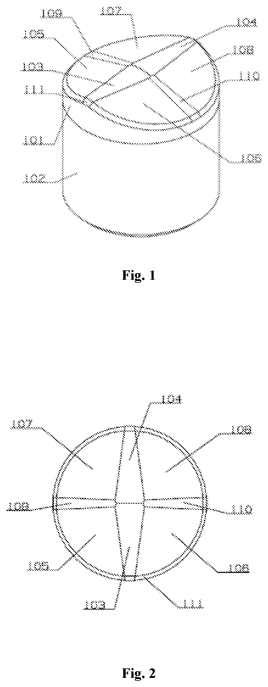
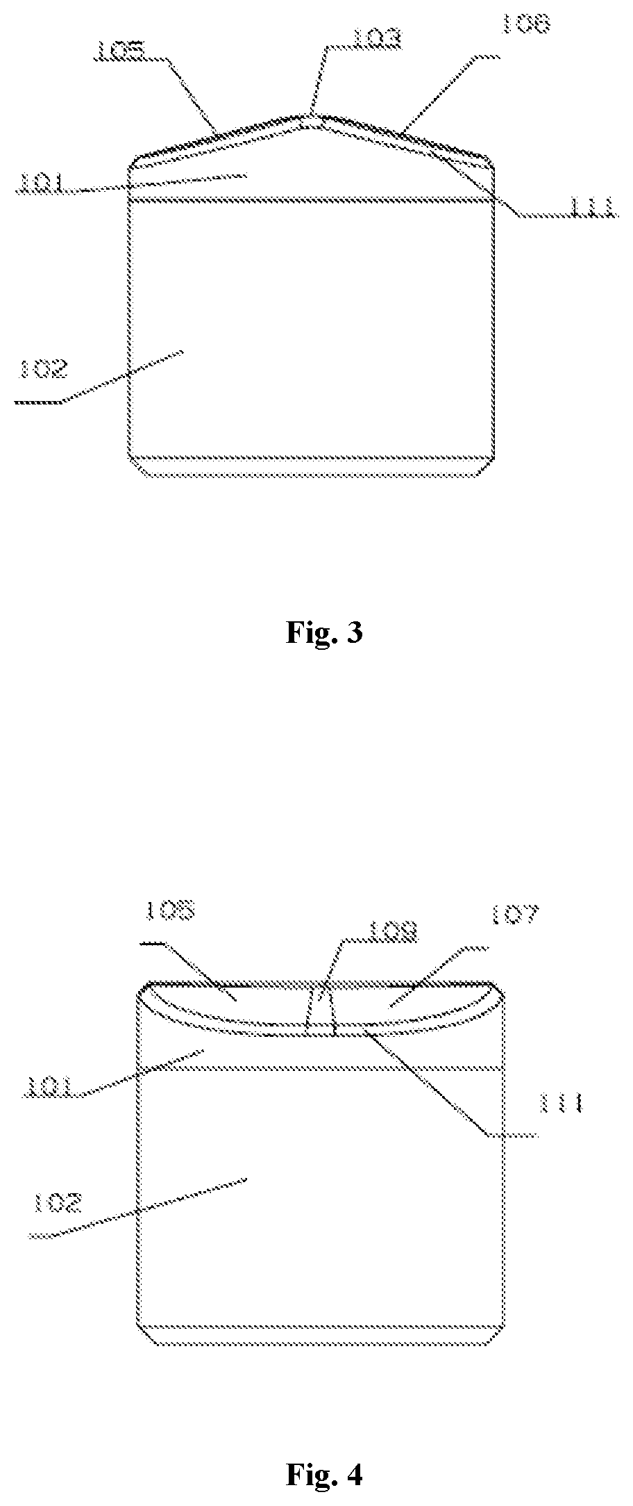
[0027]Referring from FIG. 1 to FIG. 4, the polycrystalline diamond compact comprises a diamond layer 101 and a cemented carbide substrate 102, the diamond layer 101 is disposed on the top face of the cemented carbide substrate 102, the end face of the diamond layer 101 having two continuous varying cambered convex ridges 103, 104, two continuous varying cambered convex ridges 103, 104 extend inward and intersect at the center of the end face, with the width of each continuous varying cambered convex ridges 103, 104 gradually increasing from the edge of the end face to the center of end face.
[0028]In some embodiments, the curvature radius of each continuous varying cambered convex ridges 103, 104 gradually increases or keeps constant from the edge of the end face to the center of the end face.
[0029]In some embodiments, the top face of each of continuous varying cambered convex ridges 103, 104 is parallel to the bottom face of cemented carbide substrate 102. As shown in FIG. 4, the he...
second embodiment
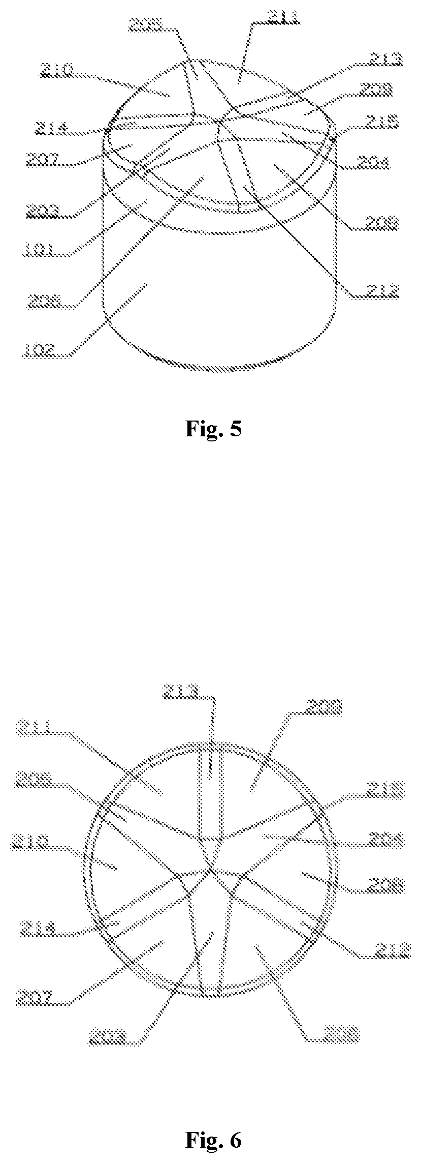
[0041]As shown from FIG. 5 to FIG. 8, there are three continuous varying cambered convex ridges 203, 204 and 205 at the end face of the diamond layer, with continuous varying cambered convex ridges extending from the edge of the end face and intersecting at the center of end face, three continuous varying cambered convex ridges are evenly distributed circumferentially, that is, the central angle between two adjacent continuous varying cambered convex ridges is 120°. Flanks 206, 207; 208, 209; 210, 211 are disposed at both sides of each of the continuous varying cambered convex ridges respectively, and each of the transitional arc surfaces 212, 213, 214 is disposed between two flanks, which are located between two adjacent continuous varying cambered convex ridges, and the edge of end face is chamfered. Other structures of second embodiment are the same as first embodiment.
third embodiment
[0042]As shown from FIG. 9 to FIG. 12, the difference from the first embodiment is: there are 4 continuous varying cambered convex ridges evenly circumferentially distributed at the end face of the diamond layer, that is, the central angle between two adjacent continuous varying cambered convex ridges is 90°.
PUM
 Abstract
Description
Claims
Application Information
 - R&D
- Intellectual Property
- Life Sciences
- Materials
- Tech Scout
- Unparalleled Data Quality
- Higher Quality Content
- 60% Fewer Hallucinations
Browse by: Latest US Patents, China's latest patents, Technical Efficacy Thesaurus, Application Domain, Technology Topic, Popular Technical Reports.
© 2025 PatSnap. All rights reserved.Legal|Privacy policy|Modern Slavery Act Transparency Statement|Sitemap|About US| Contact US: help@patsnap.com


