Method to identify malicious web domain names thanks to their dynamics

a dynamic and domain name technology, applied in the direction of transmission, platform integrity maintenance, electric devices, etc., can solve the problems of many local features that are not robust, and many of the features used are not robus

Active Publication Date: 2018-11-29
QATAR FOUND
View PDF0 Cites 46 Cited by
  • Summary
  • Abstract
  • Description
  • Claims
  • Application Information

AI Technical Summary

Benefits of technology

[0021]According to another aspect of the present invention, there is provided a system for detecting malicious domains, the system comprising: a processor; and a memory configured to store domain data for a plurality of domains and a relationship parameter which represents a relationship between at least two of the domains, wherein the memory stores machine readable instructions which, when executed by the processor, cause the processor to: generate a graph for the domains by: identifying a plurality of domain nodes which each correspond to one of the plurality of domains; connecting the domain nodes with a plurality of edges, each edge connecting two domain nodes that are related to one another by the selected relationship parameter; and calculating an edge weight for each edge which represents the strength of the relationship between the domains of the domain nodes connected by the edge; wherein the machine readable instructions, when executed by the processor, further cause the processor to: identify at least one domain node as a known malicious domain node and the other domain nodes as candidate domain nodes; calculate a malicious score for each candidate domain node based on the edge weight of each edge connecting the candidate domain node to a known malicious domain node; and identify a domain in the plurality of domains as malicious if the malicious score for the candidate domain node of the domain is within a predetermined range of malicious scores.

Problems solved by technology

However, it has been shown that many of the features used are not robust [12].
However, one problem with this conventional approach is that many local features (e.g. domain name patterns and temporal patterns) tend to be not robust.

Method used


Image

  • Method to identify malicious web domain names thanks to their dynamics
  • Method to identify malicious web domain names thanks to their dynamics
  • Method to identify malicious web domain names thanks to their dynamics

Examples


example 3.1

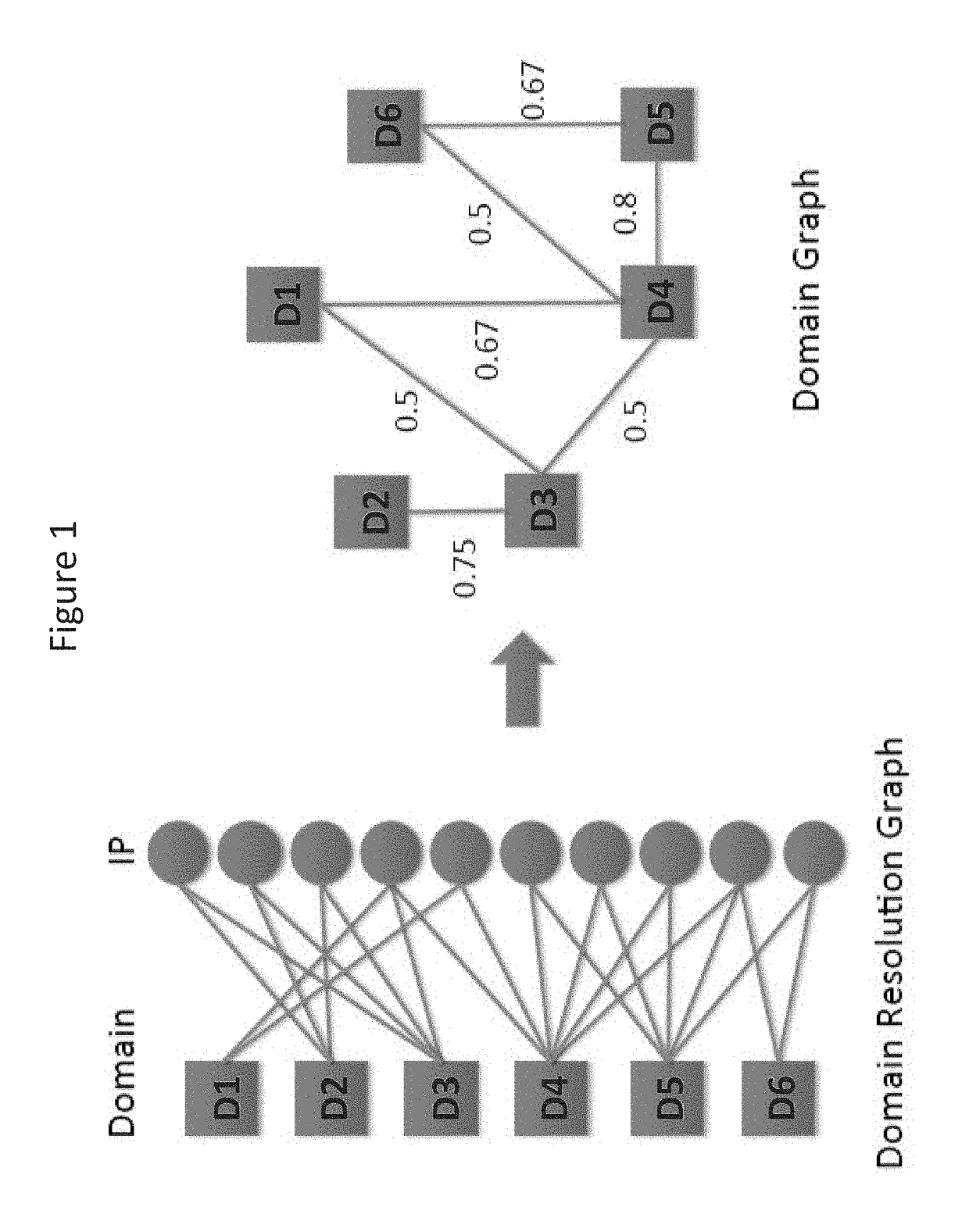
[0094]Consider the simple domain graph in FIG. 1. Assume D3 and D5 are known to be malicious, i.e., S={D3, D5}, and one would like to compute mal(D1, S). One can see that the strongest path between D1 and D3 is simply the edge connecting them. Therefore, assoc (D1, D3)=0.5. Similarly, the strongest path between D3 and D5 is (D3, D4 D5) and so assoc(D1, D5)=0.536. Then, since assoc(D1, D5)>assoc(D1, D3), we have mal(D1,S)=0.536+(1-0.536)×0.5×½1=0.625. One can compute similarly that mal(D2,S)=0.788, mal(D4,S)=0.85 and mal(D6,S)=0.714. If one sets the threshold t=0.75, D2 and D4 will be flagged as potential malicious domains.

Practical Considerations

[0095]The above description of some embodiments is based on the observation that a strong association between two domains exists if they are hosted at many common IPs in a period of time. This association may suggest that they are controlled by the same owner. For example, a botnet master may deploy phishing websites among a subset of bots i...


PUM


Abstract

Methods and systems for detecting malicious domains. The method comprises storing domain data for a plurality of domains and selecting a relationship parameter which represents a relationship between at least two of the domains. The method further comprises generating a graph for the domains by identifying a plurality of domain nodes, connecting the domain nodes with a plurality of edges and calculating an edge weight for each edge. The method further comprises identifying at least one domain node as a known malicious domain node and the other domain nodes as candidate domain nodes, calculating a malicious score for each candidate domain node based on the edge weights and identifying a domain in the plurality of domains as malicious if the malicious score is within a predetermined range.

Description

FIELD OF THE INVENTION[0001]The present invention relates to methods and systems for detecting malicious domains. The present invention more particularly relates to determining sources of malicious network traffic.BACKGROUND OF THE INVENTION[0002]Malicious domains are key components in a variety of different cyberattacks, such as phishing, botnet, command and control and spams. It is therefore important to be able to discover and block access to these attack enablers.[0003]Many techniques have been proposed to identify malicious domains, utilizing different types of local network and host information [1, 3, 8]. DNS data has been exploited in some of these efforts. The general conventional approaches extract multiple features from DNS records as well as DNS queries and responses, which may further be enhanced with historical patterns and network traffic features of local hosts (those issuing DNS queries). Based on these features and some training datasets, a classifier can be built t...

Claims


Application Information

Patent Timeline
Patent Type & Authority Applications(United States)
IPC IPC(8): H04L29/06H04L29/12
CPCH04L63/1425H04L61/2007H04L61/1511H04L63/1416G06F21/56H04L61/4511
Inventor KHALIL, ISSAYU, TINGDACIER, MARC C.
Owner QATAR FOUND
Why Eureka
Try Eureka