Eureka AIR delivers breakthrough ideas for toughest innovation challenges, trusted by R&D personnel around the world.

Display device and display method

Active Publication Date: 2018-12-13
COMPAL ELECTRONICS INC
View PDF4 Cites 3 Cited by
  • Summary
  • Abstract
  • Description
  • Claims
  • Application Information

AI Technical Summary

Benefits of technology

The present invention is a display device and method that can detect if there is a moving object around it and decide to show or not show a projection picture accordingly. This helps to create a better user experience. The device uses an object detection sensor to determine if a moving object is within a certain distance range of the display. When a moving object is detected, the device will automatically determine if it should show or not show the projection picture. This technology ensures that the display device always provides the best user experience.

Problems solved by technology

However, along with maturity of the projection technology, the manner of projecting the projection picture by only using a projector cannot meet current use requirements any more.

Method used


Image

  • Display device and display method
  • Display device and display method
  • Display device and display method

Examples


Embodiment Construction

[0021]To make the contents of the present invention more easily and clearly understood, embodiments are described in detail below to serve as examples that can be really implemented by the present invention. Furthermore, wherever possible, elements / components / steps using same labels in the drawings and implementation modes represent same or similar parts.

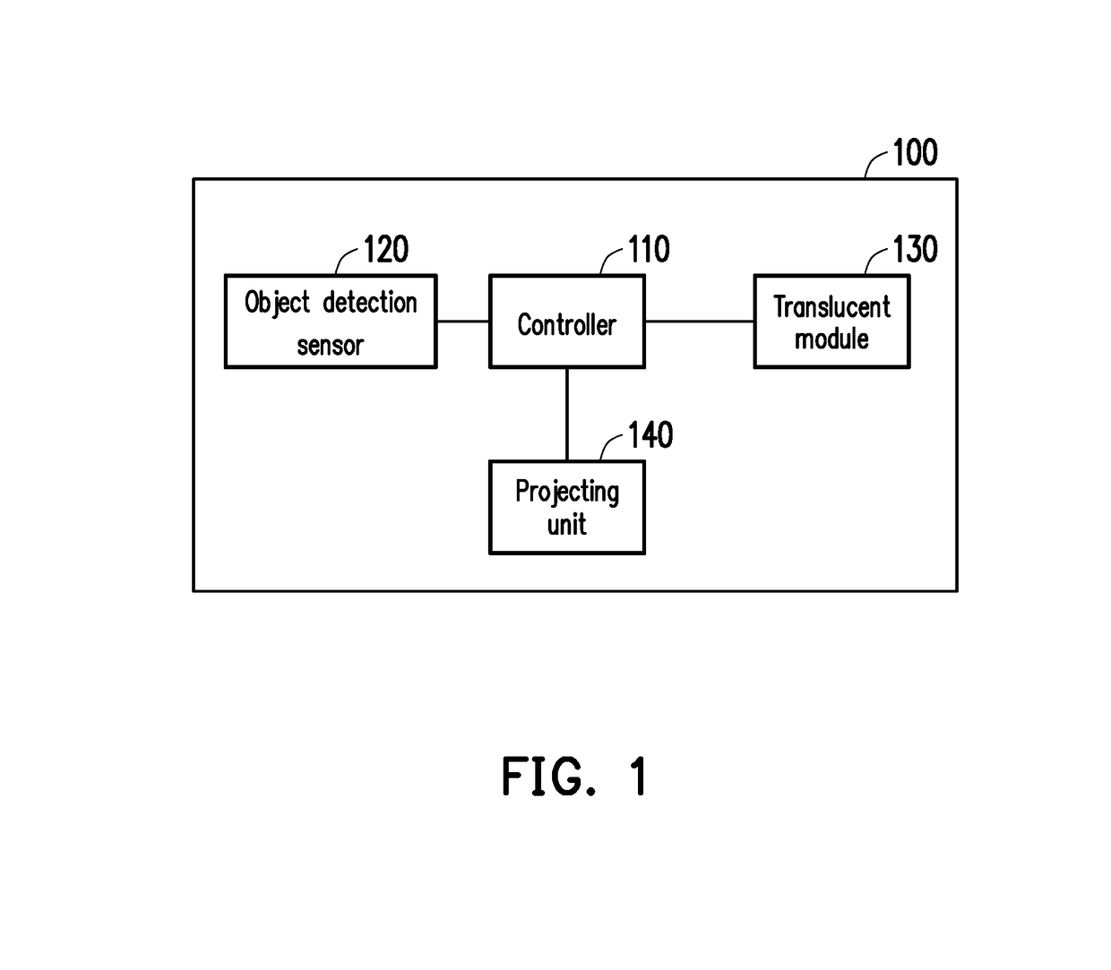
[0022]FIG. 1 is a block diagram indicating a display device of the present invention. Referring to FIG. 1, the display device 100 comprises a controller 110, an object detection sensor 120, a translucent module 130 and a projecting unit 140. The controller 110 is coupled to the object detection sensor 120, the translucent module 130 and the projecting unit 140. In the present embodiment, the object detection sensor 120 is configured to sense whether a moving object (for example, a user) exists around the housing of the display device 100, so as to output an object sensing signal to the controller 110. When the object detection senso...


PUM


Abstract

A display device and a display method are provided. The display device comprises a housing, a translucent module, a projecting unit and an object detection sensor. The housing comprises a containing space. The translucent module is disposed on the surface of the housing. The projecting unit is disposed in the containing space, and coupled to a controller. The projecting unit is configured to project projection light to the translucent module. The object detection sensor is disposed on the display device and coupled to the controller. When the object detection sensor senses that a moving object exists in a first preset distance range away from the housing, the object detection sensor outputs an object sensing signal to the controller. The controller controls the projecting unit and the translucent module based on the object sensing signal, so as to project a projection picture.

Description

CROSS-REFERENCE TO RELATED APPLICATION[0001]This application claims the priority benefit of U.S. provisional application Ser. No. 62 / 510,731, filed on May 24, 2017. The entirety of the above-mentioned patent application is hereby incorporated by reference herein and made a part of this specification.BACKGROUND OF THE INVENTION1. Field of the Invention[0002]The present invention relates to a display technology, and particularly relates to a display device with a projection function and a display method.2. Description of Related Art[0003]Generally, a display device with a projection function means that a projector is configured to project an image picture to a projection surface, so that the corresponding projection picture is displayed on the projection surface. However, along with maturity of the projection technology, the manner of projecting the projection picture by only using a projector cannot meet current use requirements any more. For example, in order to obtain better use ex...

Claims


Application Information

Patent Timeline
IPC IPC(8): G09G3/00G06F3/01G03B21/14G03B21/28
CPCG09G3/002G06F3/013G03B21/142G03B21/28G03B21/145G06F3/017H04N13/363H04N13/398G06F1/1601G03B21/14G09G3/001G09G3/003G03B17/54G03B21/10H04N9/3179H04N9/3194G06F3/0304H05K5/0017H05K5/0217H05K5/0234
Inventor LIN, HSIU-HANGCHOU, PIN-YUCHEN, KAI-YICHANG, KUN-HSUANCHENG, HSIN-CHIEHTSENG, YU-HAOWENG, CHIA-SHINTSAI, DAI-YUN
Owner COMPAL ELECTRONICS INC
Why Eureka
Eureka Blog
Learn More