Connector

a technology of connecting parts and connectors, applied in the direction of coupling contact members, coupling device connections, electrical devices, etc., can solve the problems of increasing the entire size of the connector, reducing and shaving the insulation part, so as to improve the human body contact prevention function

Active Publication Date: 2018-12-13
YAZAKI CORP
View PDF1 Cites 3 Cited by
  • Summary
  • Abstract
  • Description
  • Claims
  • Application Information

AI Technical Summary

Benefits of technology

[0008]According to the connector of the present invention described above, the tip end insulation part provided to the end face of the terminal fitting main body is receded with respect to the contact face which contacts with the mating terminal, thereby preventing the slide-contact between the insulation part and the mating terminal when connecting the connectors to each other. Further, the side insulation parts provided so as to sandwich the tip end insulation part and the terminal fitting part in the width direction are protruded with respect to the tip end insulation part, so a finger of an operator is unlikely to reach to the contact face, thereby improving the human body contact prevention function.

Problems solved by technology

However, as mentioned below, there is a drawback in the connector as disclosed in JP'809 in which the terminal is housed in the tubular housing with one end opened.
However, such configuration causes an increase in the entire size of the connector.
However, in case a connector in which a mating terminal shaped into an elastic piece is to be contacted to a band-shaped terminal fitting, the mating terminal slide-contacts (contacts in a sliding manner) on the insulation part when connecting the connectors to each other, possibly causing the insulation part to be shaved.
It is possible to bring back the insulation part from the contact face of the terminal fitting (i.e., position the insulation part away from the mating terminal) to prevent the slide-contact with the mating terminal, however that would make the finger likely to reach to the contact face, resulting in a decrease in the human body contact prevention function.

Method used


Image

  • Connector
  • Connector
  • Connector

Examples


Embodiment Construction

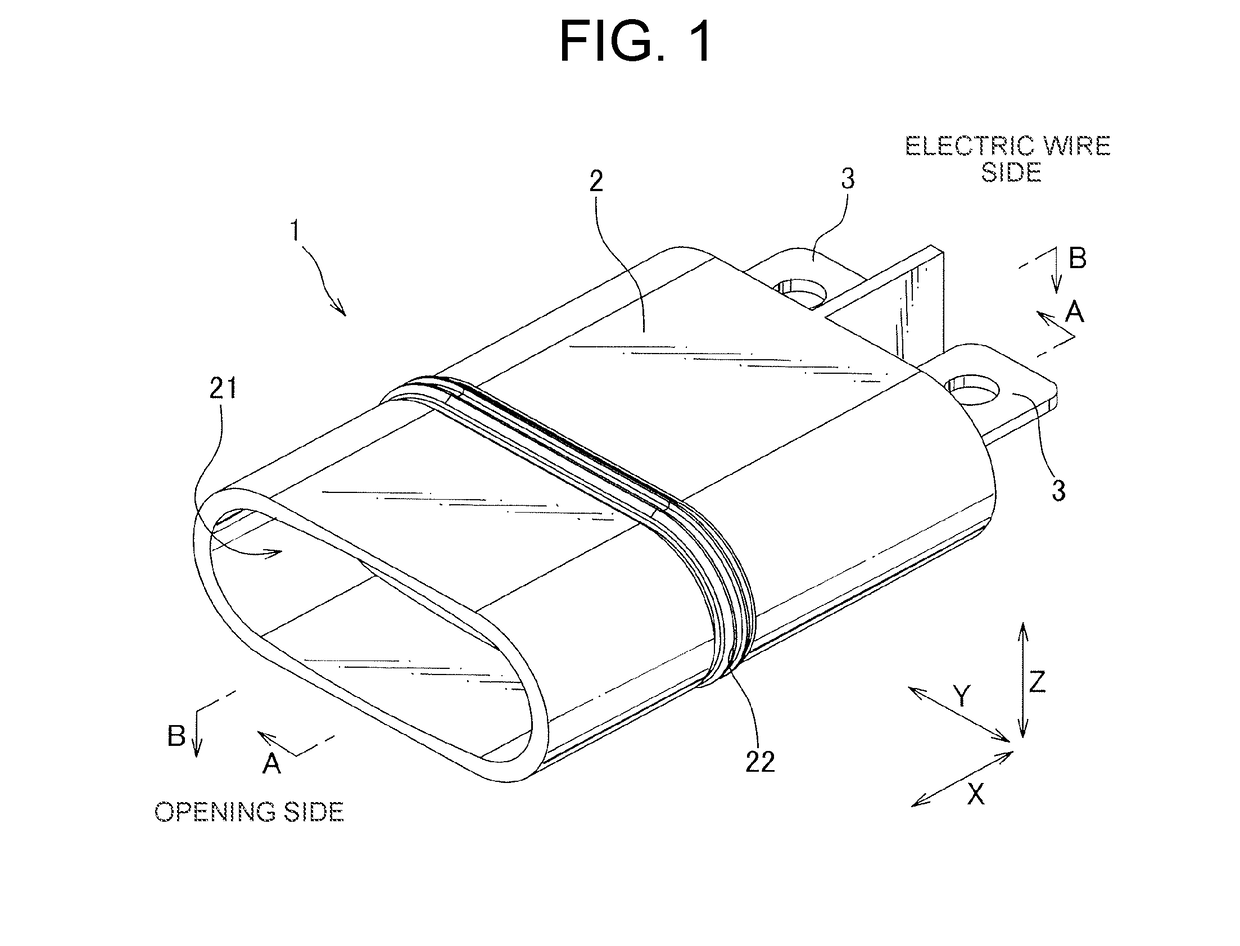
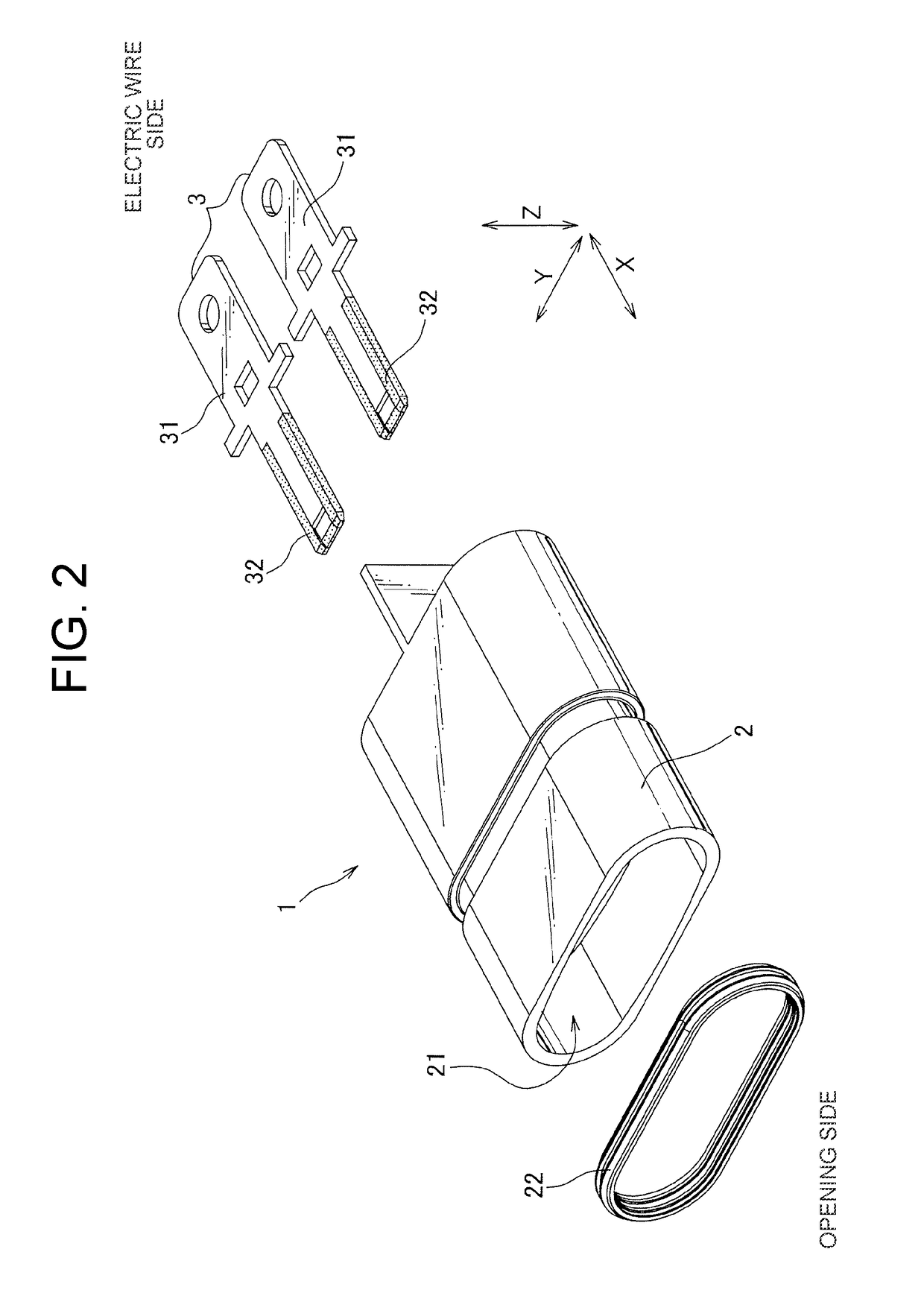
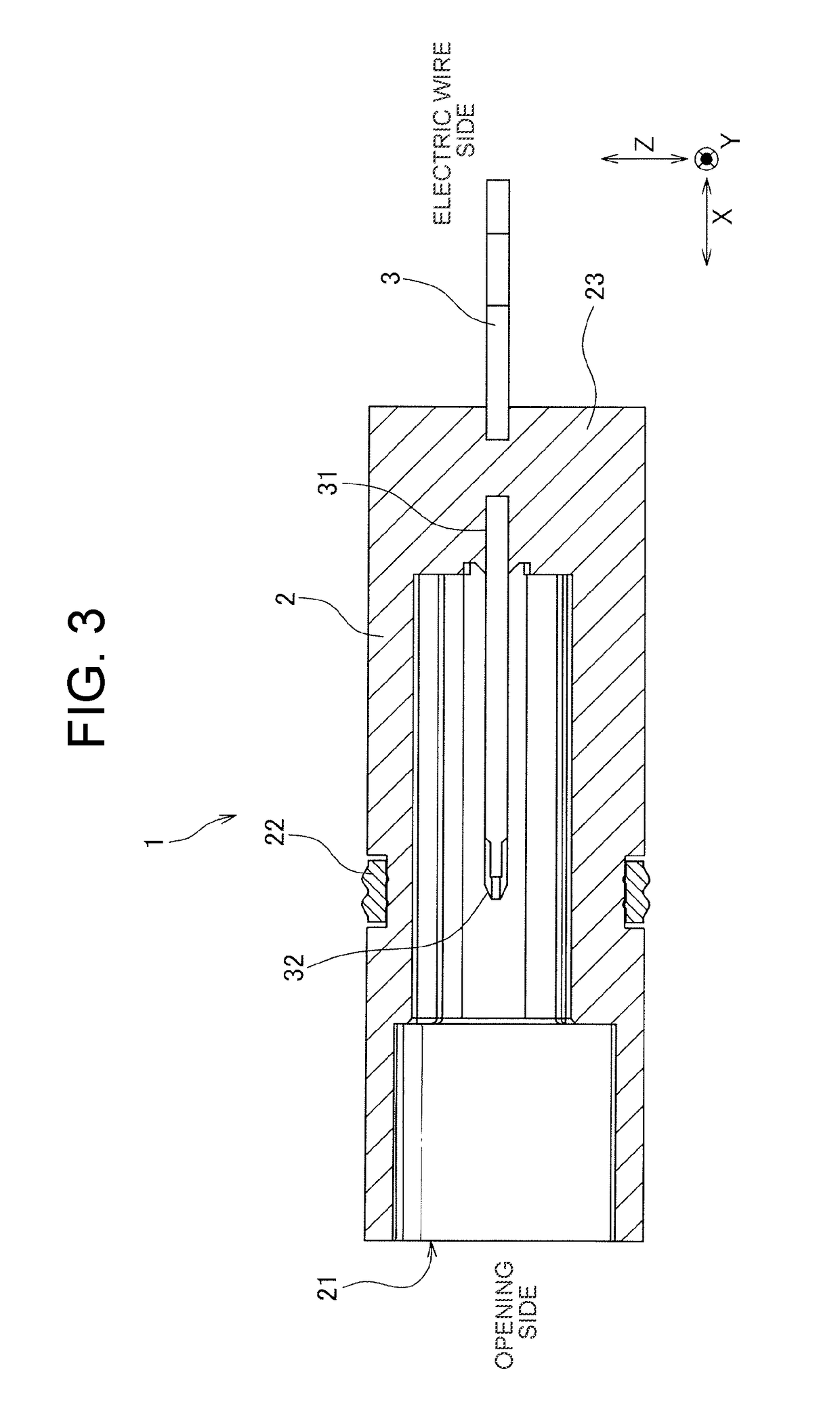
[0016]The following will explain an exemplary embodiment of the present invention in reference to the drawings. FIG. 1 is a perspective view showing a connector 1 according to one embodiment of the present invention, FIG. 2 is an exploded perspective view of the connector 1, FIG. 3 is a cross-sectional view taken along a line A-A of FIG. 1, FIG. 4 is a cross-sectional view taken along a line B-B of FIG. 1, FIG. 5 is a planar view showing a terminal 3 of the connector 1, FIG. 6 is a front view of the terminal 3, and FIG. 7 is a cross-sectional view illustrating slide-contact between the terminal 3 and a mating terminal 100.

[0017]The connector 1 according to this embodiment is for connecting on-board devices, such as a motor and an inverter, to each other. The connector 1 includes a tubular housing 2 having an opening 21 at its one end, and two terminals 3 housed in the housing 2. In this embodiment, an extending direction of the tubular housing 2 is referred to as a X direction, and ...


PUM


Abstract

Provided is a connector which can prevent slide-contact between an insulation part and a mating terminal while improving a human body contact prevention function. A tip end insulation part provided to an end face of a terminal fitting main body is receded with respect to a contact face which contacts with a mating terminal, thereby preventing the slide-contact between an insulation part and a mating terminal when connecting the connectors to each other. Further, a side insulation parts provided so as to sandwich the tip end insulation part in the Y direction are protruded with respect to the tip end insulation part, so a finger of an operator is unlikely to reach to the contact face, thereby improving the human body contact prevention function.

Description

CROSS REFERENCE TO RELATED APPLICATION[0001]The priority application Japanese Patent Application No. 2017-115436 upon which this patent application is based is hereby incorporated by reference.BACKGROUNDField of the Invention[0002]The present disclosure relates to a connector including a tubular housing and a terminal to be housed in the housing.Description of the Related Art[0003]Generally, an electrical device of an on-board device and such is provided with various connectors, and the electrical device is connected to an external device via the connectors to supply power to or transmit signal to the electrical device. As one example of such connector, there is proposed a connector to be provided to an electric throttle valve control device (for example, refer to Japanese Patent Application Publication No. 2015-83809 (hereinafter called “JP'809”)). The connector disclosed in JP'809 is constituted of a tubular coupler (housing) formed on an outer face of a cover and a coupler termin...

Claims


Application Information

Patent Timeline
Patent Type & Authority Applications(United States)
IPC IPC(8): H01R13/44H01R13/26
CPCH01R13/44H01R13/26H01R13/15H01R13/24H01R13/502H01R13/405H01R13/03H01R13/035
Inventor YAMANASHI, DAISUKEOKAMOTO, KENICHI
Owner YAZAKI CORP
Why Eureka
Try Eureka