
Model predictive control systems and methods for increasing computational efficiency

a predictive control and control system technology, applied in electrical control, program control, instruments, etc., can solve the problems of not updating the response outputs of control variables in feedback loops quickly enough to provide close to real-time feedback, traditional engine control systems do not provide a rapid response to control signals or coordinate engine torqu

Active Publication Date: 2018-12-20
GM GLOBAL TECH OPERATIONS LLC
View PDF0 Cites 6 Cited by
  • Summary
  • Abstract
  • Description
  • Claims
  • Application Information

AI Technical Summary

Benefits of technology

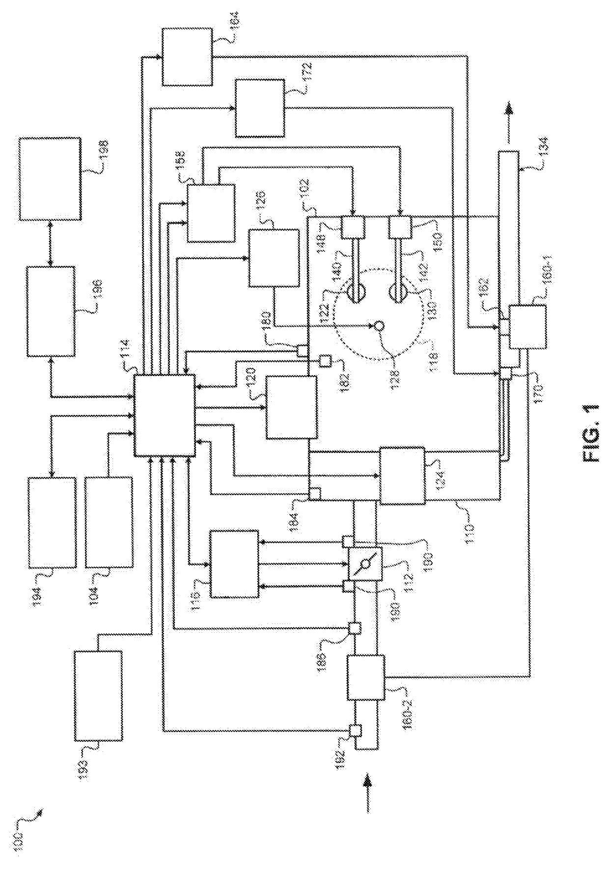
[0002]Internal combustion engines combust an air and fuel mixture within cylinders to drive pistons, which produces drive torque. Air flow into the engine is regulated via a throttle. More specifically, the throttle adjusts throttle area, which increases or decreases air flow into the engine. As the throttle area increases, the air flow into the engine increases. A fuel control system adjusts the rate that fuel is injected to provide a desired air / fuel mixture to the cylinders and / or to achieve a desired torque output. Increasing the amount of air and fuel provided to the cylinders increases the torque output of the engine.
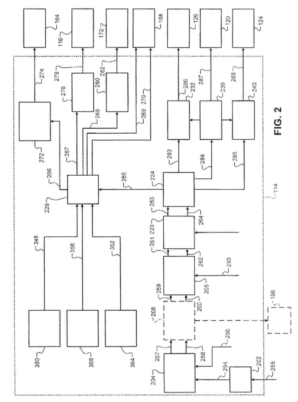
[0008]In yet another aspect of the present disclosure, optimizing a cost function further includes minimizing an actuator performance criterion over a prediction horizon for each control loop.

Problems solved by technology

Traditional engine control systems, however, do not control the engine output torque as accurately as desired.
For example, some response outputs that are used in feedback loops for control variables do not update quickly enough to provide close to real time feedback to allow for accurate commands.
Further, traditional engine control systems do not provide a rapid response to control signals or coordinate engine torque control among various devices that affect the engine output torque.

Method used


Image

  • Model predictive control systems and methods for increasing computational efficiency
  • Model predictive control systems and methods for increasing computational efficiency
  • Model predictive control systems and methods for increasing computational efficiency

Examples


Embodiment Construction

[0033]The following description is merely exemplary in nature and is not intended to limit the present disclosure, application, or uses.

[0034]As is described in U.S. Pat. Nos. 9,599,053 and 9,605,615, hereby incorporated by reference in their entirety, an engine control module (ECM) controls torque output of an engine. More specifically, the ECM controls actuators of the engine based on target values, respectively, determined based on a requested amount of torque. For example, the ECM controls intake and exhaust camshaft phasing based on target intake and exhaust phaser angles, a throttle valve based on a target throttle opening, an exhaust gas recirculation (EGR) valve based on a target EGR opening, and a wastegate of a turbocharger based on a target wastegate duty cycle.

[0035]The ECM could determine the target values individually using multiple single input single output (SISO) controllers, such as proportional integral derivative (PID) controllers. However, when multiple SISO con...


PUM


Abstract

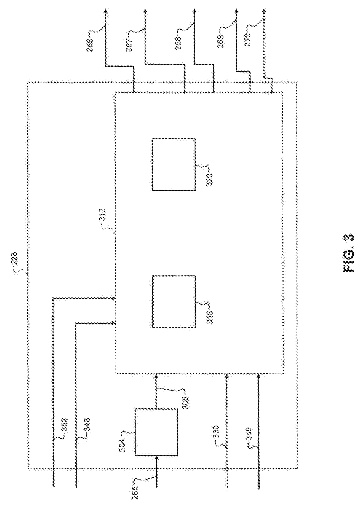
A method for controlling an actuator system of a motor vehicle includes utilizing a model predictive control (MPC) module with an MPC solver to determine optimal positions of a plurality of actuators subject to constraints, optimizing a cost function for a set of actuator duty cycles for controlling positions of the plurality of actuators, determining if the MPC solver has determined optimal actuator positions for the plurality of actuators, and applying a linear quadratic regulator (LQR) solution if the MPC solver fails to determine optimal actuator positions for the plurality of actuators.

Description

INTRODUCTION[0001]The present disclosure relates to internal combustion engines and more particularly to engine control systems and methods for vehicles.[0002]Internal combustion engines combust an air and fuel mixture within cylinders to drive pistons, which produces drive torque. Air flow into the engine is regulated via a throttle. More specifically, the throttle adjusts throttle area, which increases or decreases air flow into the engine. As the throttle area increases, the air flow into the engine increases. A fuel control system adjusts the rate that fuel is injected to provide a desired air / fuel mixture to the cylinders and / or to achieve a desired torque output. Increasing the amount of air and fuel provided to the cylinders increases the torque output of the engine.[0003]In spark-ignition engines, spark initiates combustion of an air / fuel mixture provided to the cylinders. In compression-ignition engines, compression in the cylinders combusts the air / fuel mixture provided to...

Claims


Application Information

Patent Timeline
Patent Type & Authority Applications(United States)
IPC IPC(8): F02D41/14F02D9/08F02D13/02F02D41/00F02B37/18G05B19/042
CPCF02D41/1401F02D9/08F02D13/0238F02D13/0249G05B2219/42058F02B37/186G05B19/0426F02D2041/1412F02D41/0077F02D37/02F02D2250/18F02D41/0087F02D41/1406F02D13/0203F02D41/0007F02D41/005G05B13/048F02D2041/001F02D2041/0017F02D2041/142F02D2041/1433G05B2219/2637F02D13/0219Y02T10/12Y02T10/40
Inventor JIN, NINGLONG, RUIXINGPISU, NICOLA
Owner GM GLOBAL TECH OPERATIONS LLC
Learn More