Differential Bearing Arrangement For Mounting A Differential Cage

Inactive Publication Date: 2018-12-27
ZF FRIEDRICHSHAFEN AG
View PDF5 Cites 1 Cited by
  • Summary
  • Abstract
  • Description
  • Claims
  • Application Information

AI Technical Summary

Benefits of technology

[0005]It is an object of one aspect of the present invention to provide a differential bearing

Problems solved by technology

A fastening of this kind has the disadvantage that corresponding installation space must be reserved inside the ax

Method used


Image

  • Differential Bearing Arrangement For Mounting A Differential Cage
  • Differential Bearing Arrangement For Mounting A Differential Cage
  • Differential Bearing Arrangement For Mounting A Differential Cage

Examples


Example

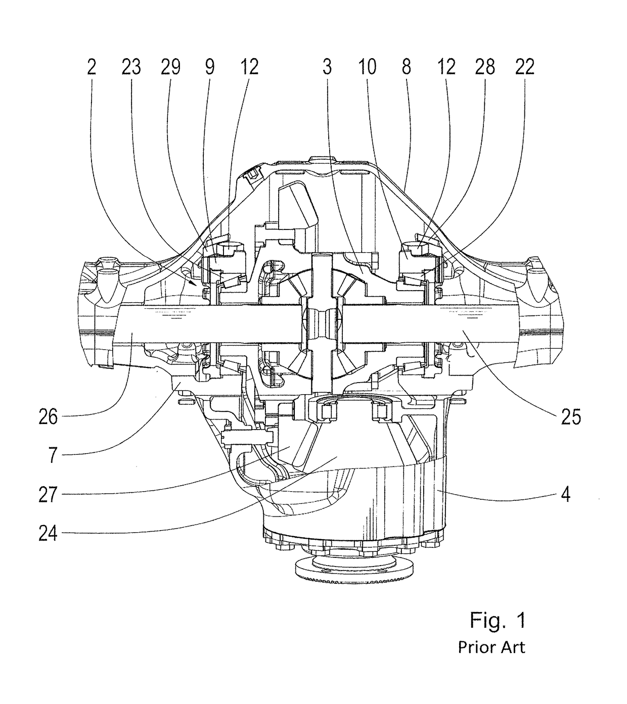
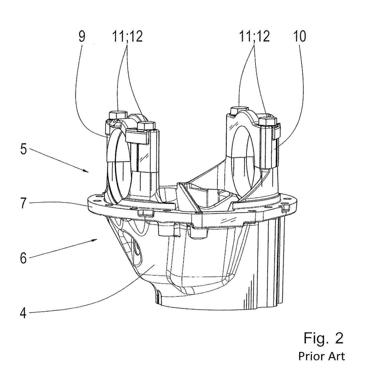
[0017]FIG. 1 shows a portion of an axle bracket of a vehicle axle according to the prior art. It comprises a differential bearing arrangement 2 that supports a differential cage 3 indirectly via bearing supports 9; 10 inside the axle bracket housing. The final drive housing 4 comprises a first portion 5 and a second portion 6. The two portions are separated from one another by a fastening collar 7. The first portion 5 is arranged inside the axle bracket such that the fastening collar 7 abuts the surface of the axle bracket 8 and is screwed to the latter. The second portion 6 of the final drive housing 4 is arranged outside of the axle bracket. Further, a bearing support 9 and a bearing support 10 are disposed inside the axle bracket 8 and are arranged at the first portion of the final drive housing 4 and fixedly connected to it by fastening screws 11. Each fastening screw 11 is arranged such that their respective screw head 12 abuts the bearing support 9. This fastening variant of t...


PUM


Abstract

A differential bearing arrangement is provided for supporting a differential cage, having a final drive housing, at least one bearing support and at least one fastening screw with a screw head and a cylindrical screw body that is provided with an external thread and fixedly connects the bearing support to the final drive housing. The bearing support has a blind hole with an internal thread and the fastening screw is arranged such that the screw head thereof comes to bear against an outer surface of the final drive housing, and the screw body extends through a through-recess formed in the final drive housing and is at least partially received by the blind hole formed in the bearing support. The internal thread of the blind hole cooperates with the external thread of the fastening screw.

Description

CROSS REFERENCE TO RELATED APPLICATIONS[0001]This is a U.S. national stage of application No. PCT / EP2016 / 077638, filed on Nov. 15, 2016. Priority is claimed on German Application No. DE102015225280.9, filed Dec. 15, 2015, the content of which is incorporated here by reference.BACKGROUND OF THE INVENTION1. Field of the Invention[0002]The invention is directed to a differential bearing arrangement for supporting a differential cage.2. Description of the Prior Art[0003]A generic differential bearing arrangement is known from DE 2006 012 342 A1. It comprises a final drive housing with a first portion and a second portion that are separated from one another by a fastening collar for fastening the final drive housing to an axle bracket of a vehicle axle. At least one bearing support, which receives the differential cage at least indirectly, is arranged at the first portion of the final drive housing. The bearing support is fixedly connected to the final drive housing by at least one faste...

Claims


Application Information

Patent Timeline
IPC IPC(8): F16H48/40
CPCF16H48/40F16H2048/405
Inventor HILDEBRAND, RAINERLENZ, PAULHASELBERGER, PETERSIGL, HORSTBAUER, MANUELBRACHMEIER, STEFAN
Owner ZF FRIEDRICHSHAFEN AG
Why Eureka
Try Eureka