Optimised three-position switch

A three-position switch and path technology, applied in the direction of electric switch, grounding switch, high voltage/high current switch, etc., can solve the problem of reducing structural space, etc., and achieve the effect of compact structure, maximized dielectric strength, and simple movement

Pending Publication Date: 2021-12-21
SIEMENS AG
View PDF18 Cites 0 Cited by
  • Summary
  • Abstract
  • Description
  • Claims
  • Application Information

AI Technical Summary

Problems solved by technology

[0004] However, if the construction space is to be reduced, and / or different insulating gases are used, then the classical construction has disadvantages with regard to insulation, construction space, drive design, cost location and other parameters

Method used


Image

  • Optimised three-position switch
  • Optimised three-position switch
  • Optimised three-position switch

Examples


Embodiment Construction

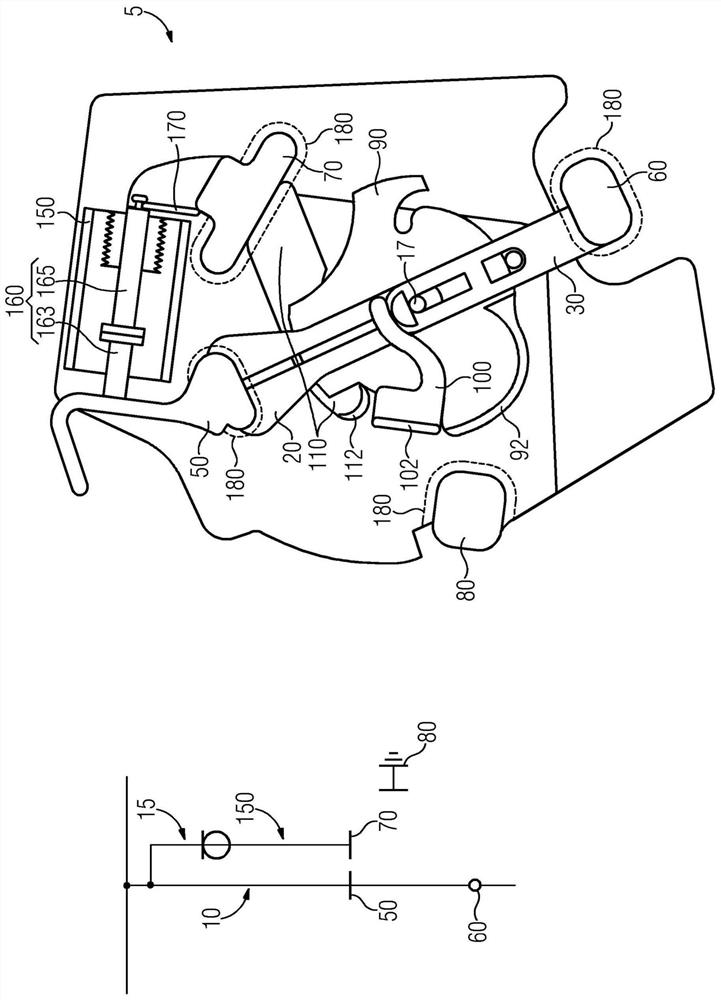
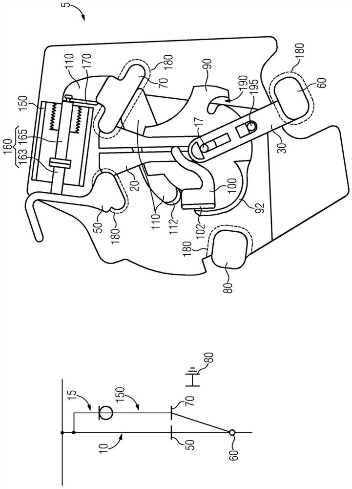
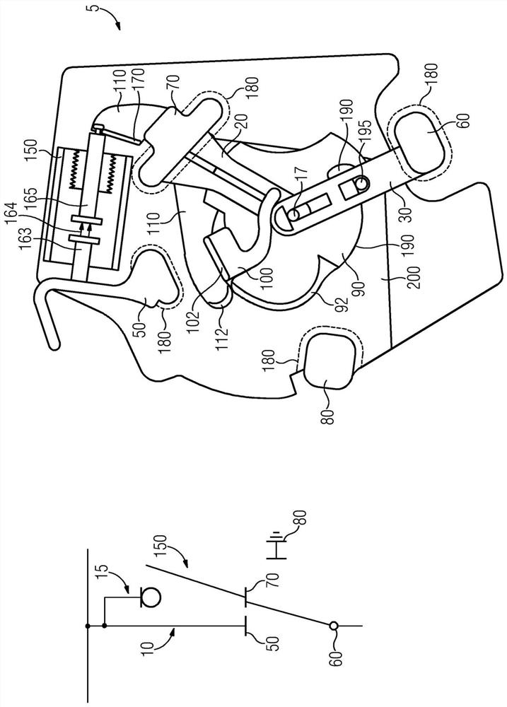
[0072] figure 1 On the left is shown the equivalent circuit diagram of a three-position switch 5 with a main current path 10, a bypass current path 15, a first main current path fixed contact 50, a second main current path fixed contact 60 , the bypass current path fixed contact 70, the grounding fixed contact 80 and the arc extinguishing device 150 (here a vacuum switching tube).

[0073] exist figure 1On the right side of , a schematic diagram of the three-position switch 5 according to the invention is shown in the "on" position. The three-position switch 5 has a bypass current path formed by an arc extinguishing device 150, and has an arc extinguishing contact 160, that is, an arc extinguishing fixed contact 163, an arc extinguishing movable contact 165, an arc extinguishing movable contact 165 and a bypass current path The contact strip 170 between the fixed contacts 70 and the bypass current path to the fixed contacts 70 . Furthermore, the three-position switch 5 has ...


PUM


Abstract

The invention relates to a switch installation, particularly for medium and/or high voltages, comprising an optimised three-position switch, and to an optimised three-position switch, wherein the three-position switch (5) comprises a main current path (10) and an auxiliary current path (15) which runs parallel to said main current path (10).

Description

technical field [0001] The invention relates to a switchgear, in particular a switchgear for medium and / or high voltage, and an optimized three-position switch, the switchgear having an optimized three-position switch. Background technique [0002] The load-disconnecting switch must be able to conduct and disconnect the nominal current of the network, wherein in the "open" switching state a defined insulation distance must be maintained. The load disconnect switch must also be able to conduct rated current as well as short-term current, be able to make short-circuit currents and be able to extinguish switching arcs. The power of a load disconnect switch is primarily defined by the rated voltage, the rated current and the nominal current (to be switched). [0003] A classic three-position switch is known, for example, from DE 10 2005 060 633 A1 for use in the SF6 environment and has a fixed contact and a moving contact. [0004] However, if the installation space is to be r...

Claims


Application Information

Patent Timeline
Patent Type & Authority Applications(China)
IPC IPC(8): H01H33/12H01H33/666H01H3/42H01H31/00
CPCH01H33/6661H01H3/42H01H31/003H01H33/122
Inventor S.霍曼D.佩施M.拉特卡R.兹利德尼克
Owner SIEMENS AG
Why Eureka
Try Eureka