
Control device, control method, and recording medium for controlling channels

Active Publication Date: 2019-01-03
JVC KENWOOD CORP A CORP OF JAPAN
View PDF11 Cites 2 Cited by
  • Summary
  • Abstract
  • Description
  • Claims
  • Application Information

AI Technical Summary

Benefits of technology

The patent describes a control device that can detect the quality of a signal received from a terminal device and transmitted from a first base station device using a first channel. When the signal quality is detected to be poor, the device can change the reception channel of a second base station device from a second channel to the first channel to prevent signal interference and improve signal quality. This allows for better communication between the base station and the terminal device. The patent has several embodiments and can be implemented in different forms such as methods, apparatuses, systems, recording mediums, and computer programs. The technical effect of this patent is to improve the quality of wireless communication by automatically adjusting the reception channel of a base station device based on the quality of the signal received from a terminal device.

Problems solved by technology

A base station may be in a state capable of transmission, but the received electric field intensity of a mobile station may not be at a level that enables demodulation so that the mobile station may not be able to receive communication from the base station.
A scheme of directing the second mobile station to change its transmission frequency to the transmission frequency of the base station device for a predetermined period of time and transmit predetermined information to the first mobile station requires complicated processes in the second mobile station, i.e., the scheme requires complicated processes in mobile stations.
Further, where mobile stations capable of performing the complicated processes and those that are not are coexistent, the mobile station that is not capable cannot be designated as the second mobile station so that it may not be able to perform the process.

Method used


Image

  • Control device, control method, and recording medium for controlling channels
  • Control device, control method, and recording medium for controlling channels
  • Control device, control method, and recording medium for controlling channels

Examples


embodiment 1

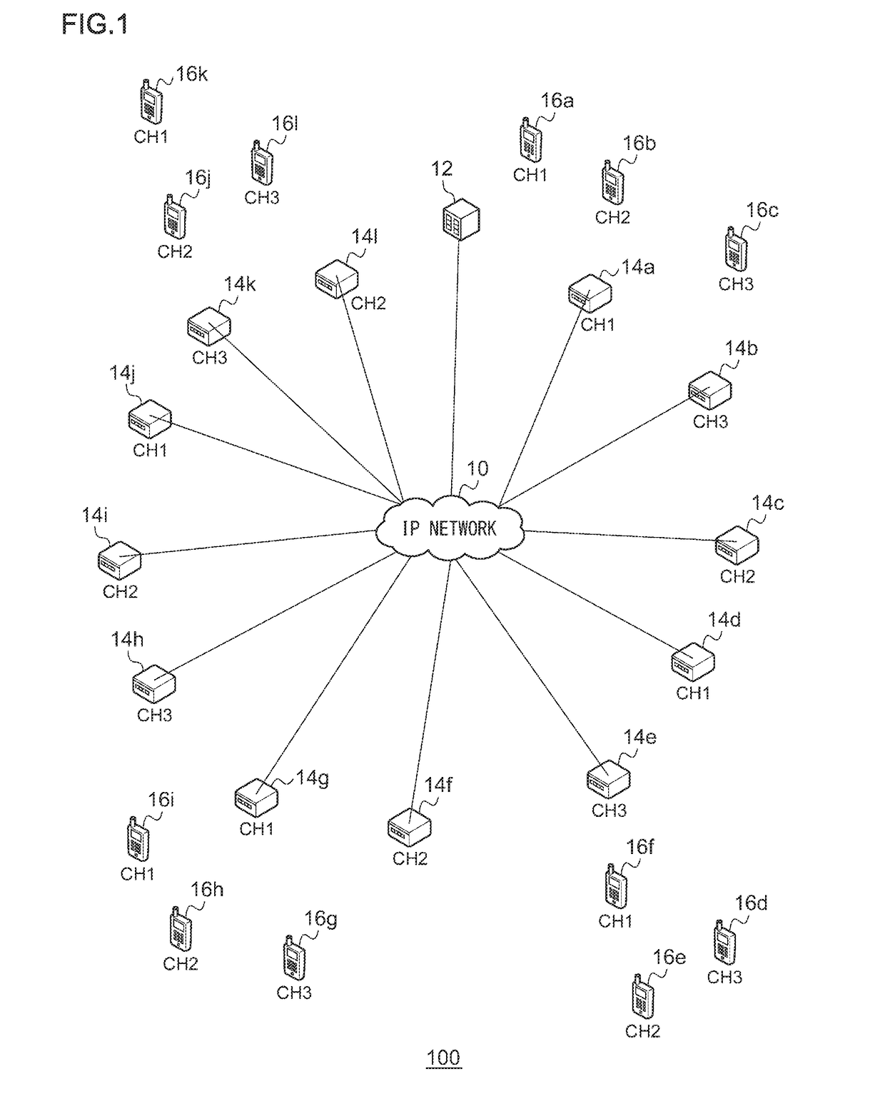
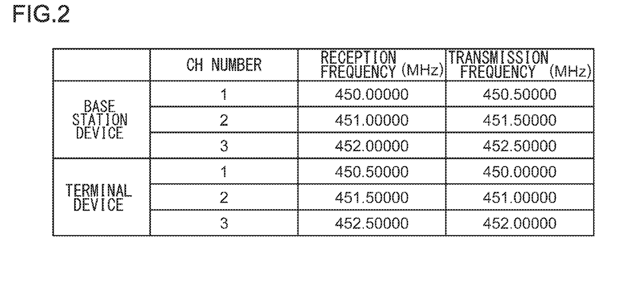
[0027]A summary will be given before describing the invention in specific details. Embodiment 1 relates to a communication system including a plurality of terminal devices configured to communicate with each other via a base station device. The communication system is compatible with, for example, a business wireless system and performs group communication. The frequency of a link from a terminal device to a base station device (hereinafter, “uplink frequency”) and the frequency of a link from a base station device to a terminal device (hereinafter, “downlink frequency”) are different. The uplink frequency corresponds to the reception frequency in the base station device, and the downlink frequency corresponds to the transmission frequency in the base station device. A plurality of uplink frequencies and a plurality of downlink frequencies are defined, and a combination of one uplink frequency and one downlink frequency are set in the base station device. Hereinafter, the combinatio...

embodiment 2

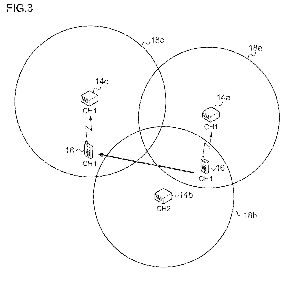
[0056]A description will now be given of embodiment 2. Like embodiment 1, embodiment 2 relates to a communication system including a plurality of terminal devices configured to communicate with each other via a base station device. As in embodiment 1, if a further base station device proximate to a base station device connected to a terminal device (terminal device subject to relief) is using a CH different from the CH that the terminal device uses, the uplink frequency of the further base station device is switched to the uplink frequency of the terminal device. In embodiment 1, such switching is performed when the further base station device is not receiving signals from further terminal devices. Meanwhile, switching in embodiment 2 is performed when the priority level of the terminal device subject to relief or the group including the terminal device subject to relief is higher than the priority level of further terminal device or the group including the further terminal device. ...


PUM


Abstract

A detector in a control device detects a quality of a signal received by a first base station device and transmitted from a terminal device using a first channel. A channel setting controller in the control device changes a reception channel of a second base station device from a second channel to the first channel when the detector detects a drop in the quality of the signal.

Description

CROSS-REFERENCE TO RELATED APPLICATION[0001]This application is based upon and claims the benefit of priority from the prior Japanese Patent Application No. 2017-129098, filed on Jun. 30, 2017, the entire contents of which are incorporated herein by reference.BACKGROUND1. Field[0002]The present invention relates to communication technologies and, more particularly, to a control device, control method, and recording medium for controlling channels.2. Description of the Related Art[0003]In a digital wireless system comprised of two types of facilities including base stations and mobile stations, pairs of uplink and downlink radio frequencies are allocated. In a digital wireless system, communication is performed between a base station and a mobile station or performed between mobile stations via a base station, using the pairs of uplink and downlink radio frequencies. A mobile station is placed in a state capable of transmission by push-to-talk, and the information transmitted from th...

Claims


Application Information

Patent Timeline
IPC IPC(8): H04W24/10H04W72/04H04W74/00
CPCH04W24/10H04W72/0406H04W74/004H04W74/006H04L1/0026H04L5/0037H04W36/08H04W36/304H04W36/322H04W36/32H04W36/30H04W72/20
Inventor SHIMOSHIMANO, HIDEOSHISHIDO, ICHIRO
Owner JVC KENWOOD CORP A CORP OF JAPAN
Learn More