
Technique for delivering content to a user

Inactive Publication Date: 2012-03-22
FRANCE TELECOM SA
View PDF155 Cites 7 Cited by
  • Summary
  • Abstract
  • Description
  • Claims
  • Application Information

AI Technical Summary

Benefits of technology

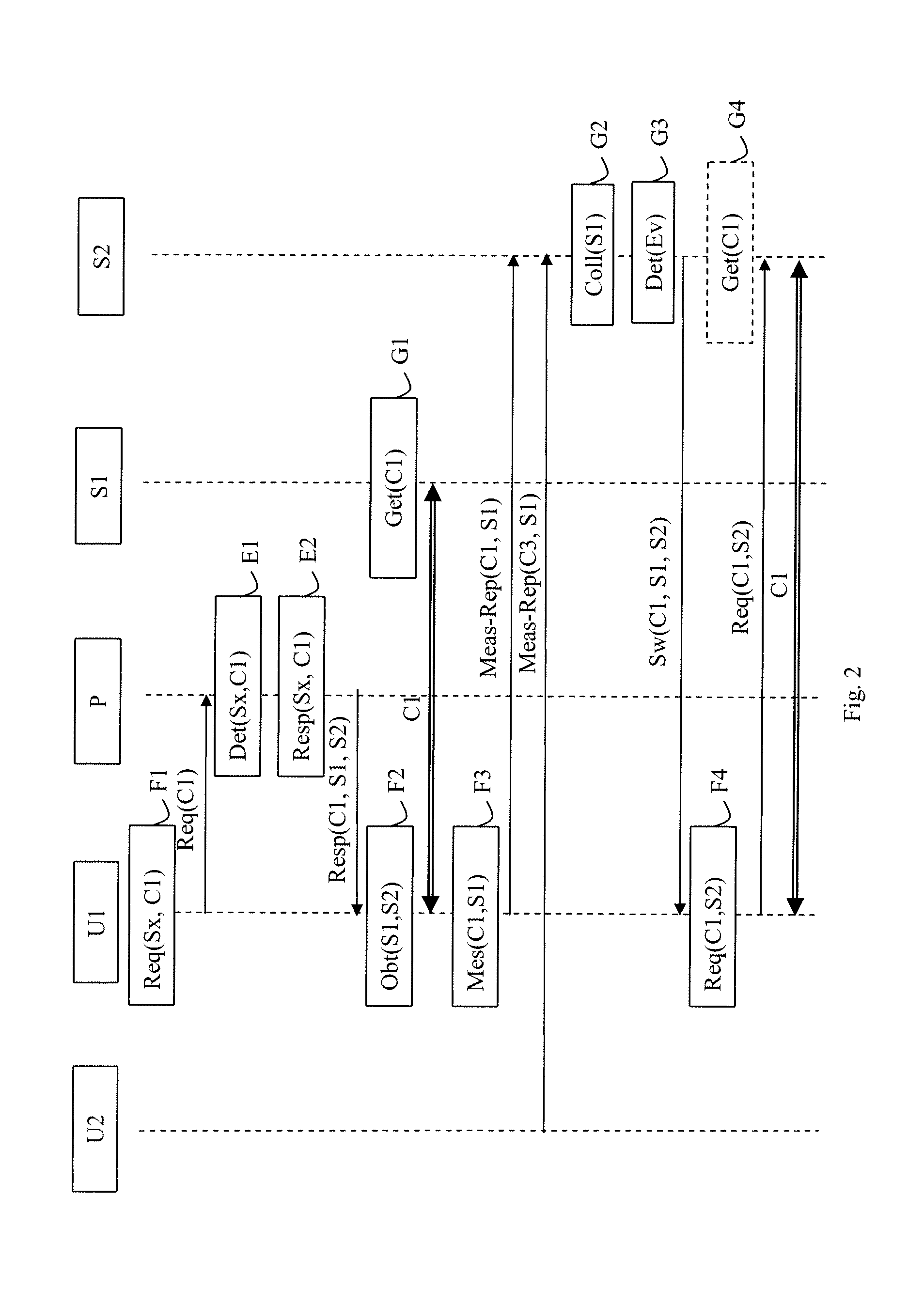
[0011]Thus, the content-delivery method enables a drop in quality to be detected on the basis of measurements performed by at least one user to which the content is being delivered from the primary device. This makes it possible to anticipate actions that need to be taken in order to guarantee reception quality for the user. The content-delivery devices may be content-delivery servers. They may also be peers in a peer-to-peer or P2P type network. The user terminal may be a P2P network peer: under such circumstances, it may perform two functions, both terminal and server.
[0012]The method is remarkable in that the secondary device is the receiver of the measurements and as a result can take over from the primary device in order to deliver the content. In conventional manner, it is the device or the peer that is delivering the content that receives the measurements performed by the user's terminal. By means of the content-delivery method of an embodiment of the invention, poor user perceptions associated with degraded quality are thus avoided, since the content-delivery method anticipates a forthcoming problem and proposes a solution, instead of responding after the problem has occurred. Thus, there is no need in such circumstances to introduce redundancy by providing a plurality of devices in order to guarantee that the desired quality will be reached. This limits the redundancy needed in the communications network. Furthermore, the processor load on the primary device delivering the content is reduced since it is not involved in collecting the measurements or in analyzing them. It is no longer both judge and judged in making the content-delivery method secure. The secondary device has processor resources available for performing those tasks. Since the path taken through the network between the user and the secondary device is, a priori, different from the path between the user and the primary device, once the session has been transferred from the primary device to the secondary device, the quality of the delivery of the content can only improve. Furthermore, supervising the quality of the delivery of the content is less complex to implement in such an architecture than in a communications network where a plurality of servers or of peers are involved in delivering the content. The supervision of the quality with which a content is delivered thus becomes deterministic and it is controlled by the network. In a network involving a plurality of servers or peers, the supervision and then the decision to change server or peer are generally performed by the terminal itself. Changes of server or of peer by a set of terminals can then give rise to oscillating loads on the links and the servers, and that can prevent the content-delivery service from being provided, even though the nominal loading of the system has not yet been reached.
[0019]In this way, the information given to the user is improved.

Problems solved by technology

This given level of quality is desired but it is not guaranteed.
Furthermore, it is difficult to measure quality, whether network quality or quality as experienced by the user, since a plurality of servers are involved in delivering the content.
The user thus perceives the drop in quality and is not satisfied.
This limits the redundancy needed in the communications network.
It is no longer both judge and judged in making the content-delivery method secure.
Since the path taken through the network between the user and the secondary device is, a priori, different from the path between the user and the primary device, once the session has been transferred from the primary device to the secondary device, the quality of the delivery of the content can only improve.
Changes of server or of peer by a set of terminals can then give rise to oscillating loads on the links and the servers, and that can prevent the content-delivery service from being provided, even though the nominal loading of the system has not yet been reached.

Method used


Image

  • Technique for delivering content to a user
  • Technique for delivering content to a user
  • Technique for delivering content to a user

Examples


Embodiment Construction

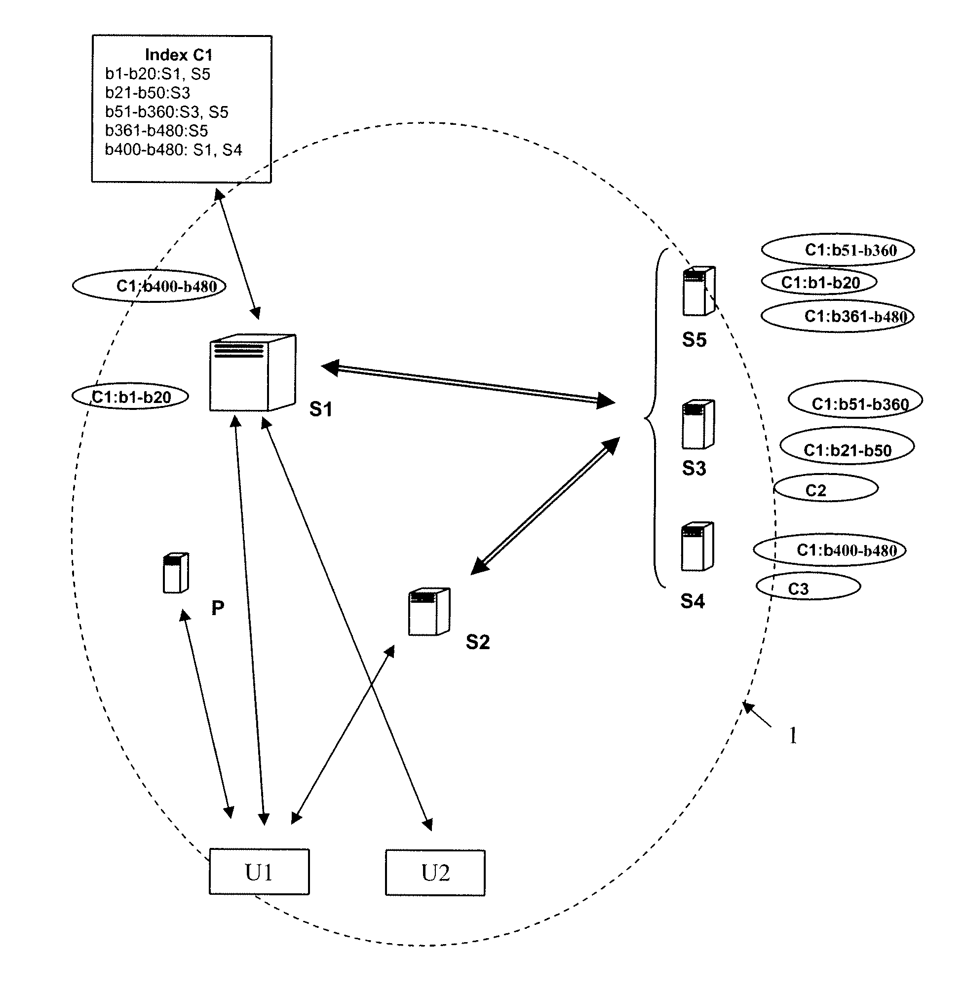
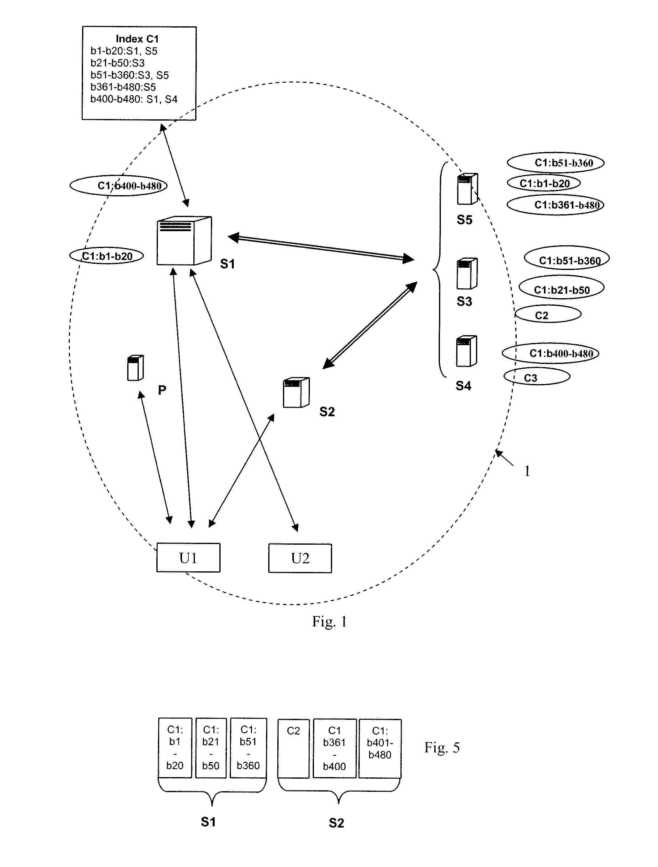
[0043]The content-delivery system 1 in its environment is described with reference to FIG. 1 in a particular embodiment.

[0044]The content-delivery system 1 comprises a plurality of content-delivery servers, two of which, S1 and S2, are shown in FIG. 1, for distributing content to a plurality of users U1, U2. Below, the same reference is used both for a terminal and for the user of the terminal. The contents for delivery are shared over the content-delivery servers S1 and S2 and content servers S3, S4, S5. The delivery servers S1, S2 and the content servers S3, S4, S5 constitute a portion of a Content Delivery Network. A CDN network is constituted by servers connected as a network via a communications network of the Internet type or any other type of network, e.g. a mobile network. These servers co-operate in order to make multimedia content or data available to users. The servers co-operate with one another in order to satisfy requests issued by users for access to content or to dat...


PUM


Abstract

A technique is provided for delivering content to a user. The user sends at least one quality indicator to a first content-delivery device, referred to as a secondary device. The indicator relates to delivery of a portion of the content by a second content-delivery device, referred to as a primary device. When the secondary device detects an event that might affect the delivery of the content by the primary device to the user, on the basis at least of the quality indicators relating to at least a delivery of content by the primary device, it commands the user to transfer from the primary device to the secondary device in order to enable the secondary device to deliver portions of the content that have not been delivered by the primary device.

Description

CROSS-REFERENCE TO RELATED APPLICATIONS[0001]This Application is a Section 371 National Stage Application of International Application No. PCT / FR2010 / 050956, filed May 18, 2010, which is incorporated by reference in its entirety and published as WO 2010 / 136699 on Dec. 2, 2010, not in English.STATEMENT REGARDING FEDERALLY SPONSORED RESEARCH OR DEVELOPMENT[0002]None.THE NAMES OF PARTIES TO A JOINT RESEARCH AGREEMENT[0003]None.FIELD OF THE DISCLOSURE[0004]The disclosure relates to a technique for delivering a content to a user by content-delivery devices.[0005]The disclosure lies in the fields of telecommunications, and more particularly in the field of content delivery.BACKGROUND OF THE DISCLOSURE[0006]Techniques exist that enable the user of a terminal to obtain content from a content-delivery server. In order to guarantee that the content is available, it is possible to obtain content from a plurality of content-delivery servers in a communications network or from peers each having ...

Claims


Application Information

Patent Timeline
IPC IPC(8): G06F15/16
CPCH04L65/4084H04L67/1012H04L67/1002H04L67/104H04L65/612H04L67/1001
Inventor STEPHAN, EMILELATTMANN, JOEL
Owner FRANCE TELECOM SA
Learn More