Method for making cases for firearms

Inactive Publication Date: 2019-01-10
BASCHIERI & PELLAGRI
View PDF19 Cites 0 Cited by
  • Summary
  • Abstract
  • Description
  • Claims
  • Application Information

AI Technical Summary

Benefits of technology

This invention provides a way to make cases for firearms without the drawbacks of previous methods.

Problems solved by technology

The compression of the reinforcing element constitutes the most critical and delicate step of the assembly process.
The process, if not controlled correctly, may however cause serious consequences.
Firstly, a non-uniform forming of the anchoring tooth, due for example to a partial elastic return of the reinforcing element, may result in the serious disassembly of the three elements of the case after firing.
Moreover, if a compression is applied on the reinforcing element with an intensity greater than planned, this may result in an excessive flattening of the pipe with a consequent weakening to the traction and, consequently, insufficient resistance during firing.
However, this solution requires machines which are just as complex due to the above-mentioned step of folding the open base.

Method used


Image

  • Method for making cases for firearms
  • Method for making cases for firearms
  • Method for making cases for firearms

Examples


Embodiment Construction

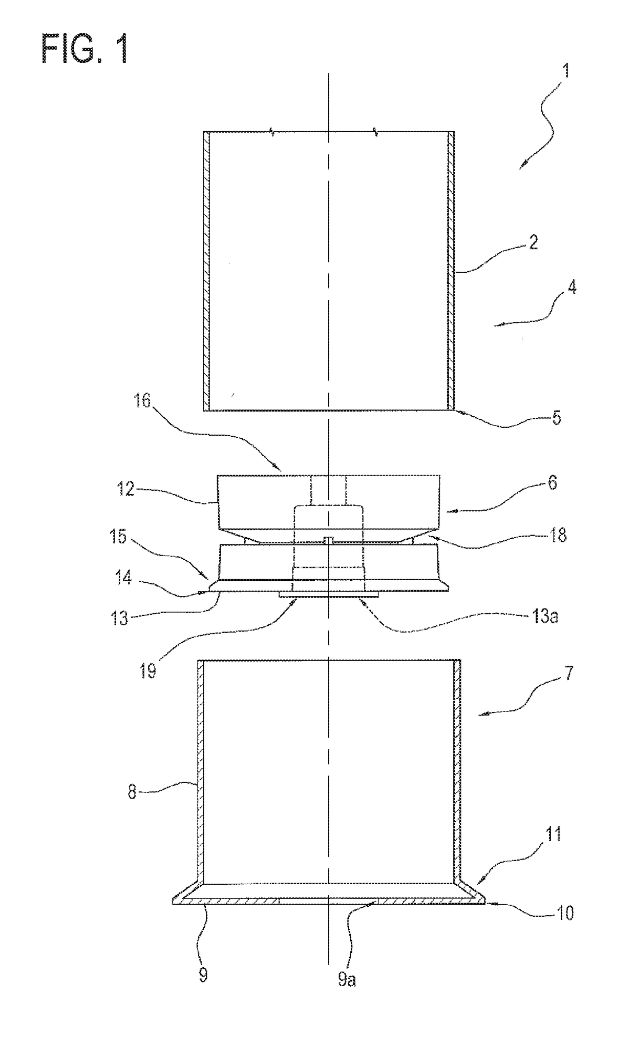
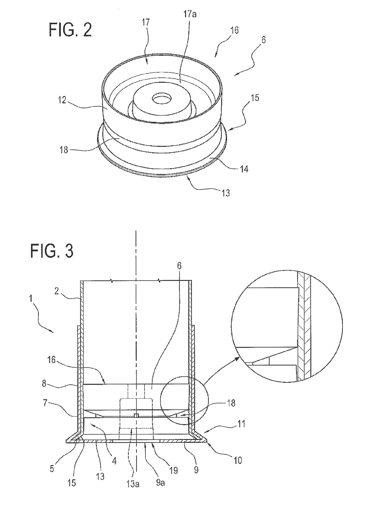
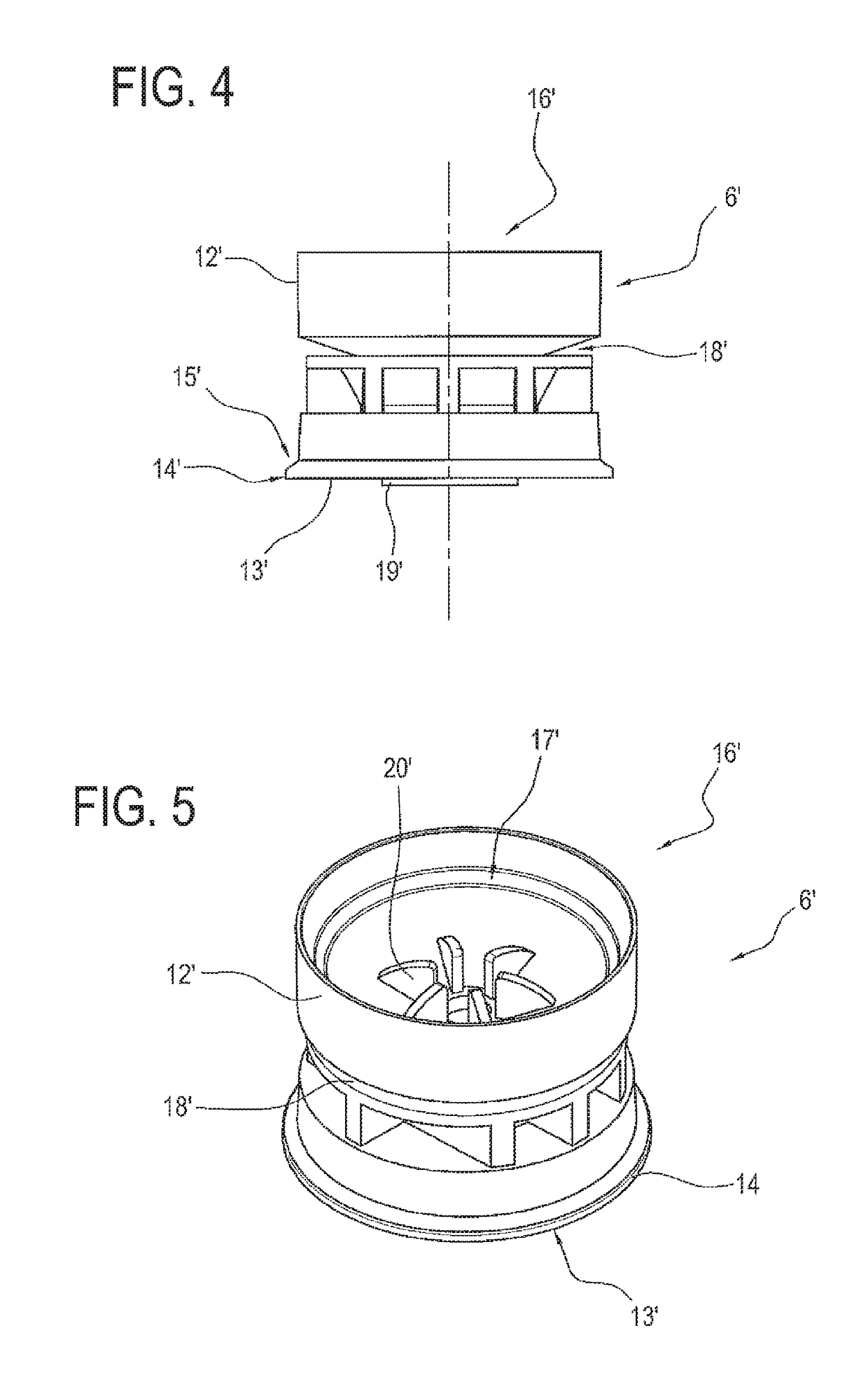
[0032]With reference to FIGS. 1 and 3, the numeral 1 denotes in its entirety a case for firearms comprising:[0033]a substantially cylindrical pipe 2, made of a rigid material and delimited, at its first longitudinal end 4, by a substantially circular end edge 5;[0034]a reinforcing element 6, made of plastically deformable material and inserted inside the first end 4 of the pipe 2; and[0035]a base 7, made of a rigid material, fitted on the first end 4 of the pipe 2 and having a substantially cylindrical shape, with a tubular side wall 8 and with a bottom wall 9 along whose perimeter edge 10 the side wall 8 is flared outwards in such a way as to form a collar 11 which has internally a seat undercut.

[0036]The pipe 2 is preferably made of plastic material or paper and is substantially non-deformable. The inside of the pipe 2 houses the gunpowder, not illustrated. On the opposite side of the first end 4, that is to say, at its second longitudinal end, the pipe 2 holds a projectile, also ...


PUM


Abstract

Described is a A method for making cases for firearms of the type comprising including a substantially cylindrical rigid pipe (2), a plastically deformable reinforcing element (6) and pre-shaped with a perimeter anchoring tooth (15), and a substantially cylindrical rigid base (7), which has a tubular side wall (8) and a bottom wall (9) along whose perimeter edge (10) the side wall (8) is flared outwards in such a way as to form a collar (11) which has internally a seat undercut; the. The method comprises includes inserting the reinforcing element (6) in the pipe (2), and both in the base (7) until they make contact the bottom wall (9) of the base (7); and axially compressing the reinforcing element (6) such a way that, by deforming plastically, it expands radially until securing the pipe (2) against the inner side wall (8) of the base (7), and until inserting the anchoring tooth (15) inside the collar (11) with the consequent radial deformation of an end edge (5) of the pipe (2), which is thus secured, in flared configuration, between the anchoring tooth (15) and the collar (11).

Description

TECHNICAL FIELD[0001]This invention relates to a method for making cases for firearms.BACKGROUND ART[0002]The cases for firearms are traditionally made by assembling in a mutually integral manner three elements:[0003]a rigid pipe, made of plastic or paper;[0004]a base made of rigid metallic material; and[0005]a reinforcing element made of deformable material, either plastic or paper, and known to experts in the field as “base wad”.[0006]The pipe is substantially cylindrical in shape, with its longitudinal end folded towards the inside, that is to say, towards the axis, in such a way as to define an annular edge.[0007]The body has a substantially cylindrical shape, with a tubular side wall and a bottom wall.[0008]Along the perimeter edge of the bottom wall, the side wall is flared outwards in such a way as to form a so-called “collar” which has internally a seat undercut.[0009]The bottom wall has a central hole through which an ignition capsule is inserted for triggering the gunpowde...

Claims


Application Information

Patent Timeline
IPC IPC(8): F42B5/307F42B33/00
CPCF42B33/001F42B5/307
Inventor MANFREDI, MARCO
Owner BASCHIERI & PELLAGRI
Why Eureka
Try Eureka